
Get Tech Tips
Subscribe to get free tech tips.
When Ducts Get Too Big

This tech tip recaps the livestream by the same name, featuring HVAC School contributors Matt Bruner and Adam Mufich, as well as special guests Russ King, Steve Rogers, and Tony Amadio. You can watch that live stream on our YouTube channel HERE.
It was a beautiful day outside. The sun was shining, the birds were singing. And THEN Ed Janowiak hopped online and said:
“Ducts can’t be too big.”
That one comment plunged the HVAC side of the internet into chaos, but it also raised an interesting question: can ducts be too big?

Unlike with HVAC units, the answer isn’t a cut-and-dry yes or no. While it is possible that ducts can be too big under a given set of conditions, the duct size itself is likely not the core issue. There’s a lot more to delivering air for maximum comfort than picking a duct size carefully or doing so haphazardly and hoping for the best.
Equivalent Length and Fittings
Roughness and obstacles (bends, transitions, boots, dampers, coils, etc.) in the ductwork create resistance that the airflow needs to overcome, and fittings provide a larger amount of resistance than the duct roughness. Airflow resistance is measured by differences in the total pressure. However, ACCA Manual
D simplifies our understanding of duct losses in the form of equivalent lengths (ELs) for fittings and total equivalent lengths (TELs) for fittings' equivalent lengths plus the duct run lengths.
Manual D gives us a range of Friction Rate (FR) values: 0.06–0.18. It helps to think of our friction rate as a “resistance budget.” It tells us how much pressure drop we can afford based on the pressure our fan gives us. Higher friction rates are typically associated with smaller ducts; smaller ducts have more friction than larger ones, and a higher friction rate is a bigger “resistance budget.” Increasing a supply branch duct diameter by one inch can increase its airflow by about 30–50%, so that’s something to keep in mind.
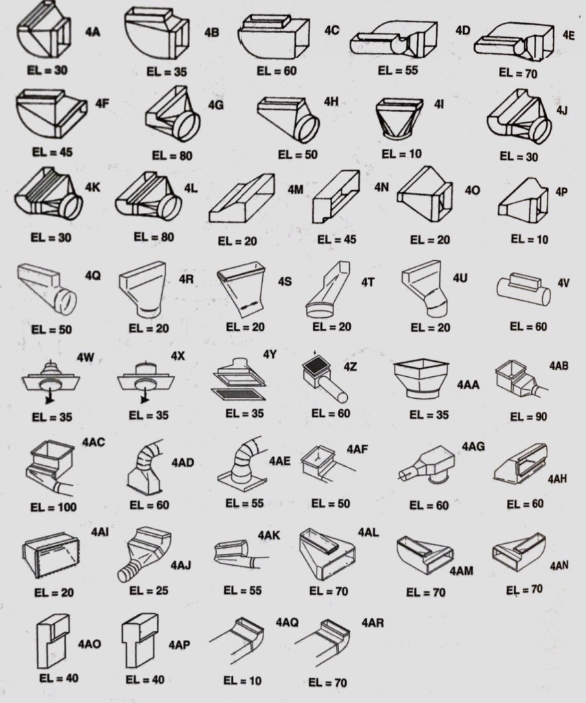
We use TEL to think about the amount of resistance the entire system gives us in terms of straight ductwork length. In other words, TEL can tell us the total pressure drop of the system when multiplied by 0.01FR. When we look at the diagram below, we can see that fittings may be equivalent to anywhere from 10 to 70 feet of straight duct, or about 0.01”w.c to 0.06” w.c.
While it is recommended to keep the TEL as low as possible, Manual D will help us out and point us toward larger ductwork to mitigate the pressure drop when that’s not possible. But that’s what raises the question: at what point do ducts become too big?
Flex Duct vs. Sheet Metal
Fittings get especially interesting when we compare flex duct and sheet metal. In Russ King’s experience, flex ductwork tends to be his go-to design, and he sees great test-out results. That’s because air naturally prefers round, sweeping bends as opposed to the 90s in sheet metal duct systems. (David Richardson from NCI had a great analogy in the livestream that he and Ed joined. HERE is that livestream, and HERE is the tech tip from it.)
Velocity and Comfort
As briefly mentioned earlier, low velocity isn’t a common problem in duct systems. However, proper air mixing partially depends on having enough velocity, and that can get low in the branches. Warm and cool air won’t mix as well as they need to, which can negatively affect comfort.
Apart from air mixing, velocity in the ducts doesn’t have much of an impact on comfort. Register sizing is far more important on that end. The air velocity in the duct upstream of the register won’t be the same as the velocity of the air exiting the register, so the branch duct size is less important as long as the registers are designed correctly.
It’s also worth mentioning that some “low velocity” issues may be due to an issue with ECM blower algorithms. When there is too little back pressure, the computer that operates the ECM may not be within a stable operating range.
However, there will be more surface area when we have bigger ducts and lower air velocities. That means we may have larger duct loads, but those are less likely to have a major impact on comfort than issues like leakage.
Duct Heat Transfer
Heat transfer in the ductwork happens via conduction (through the insulation jacket), which equals convection (between the internal air and the duct and between the external surroundings and the duct). However, Manual J overestimates the duct load since it assumes a simplified external surface area model and does not account for thermal regain (i.e., attic temperature changes due to the duct heat exchange).
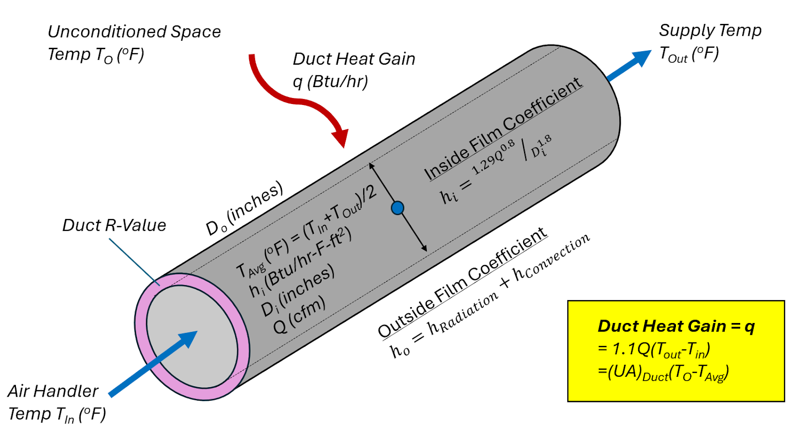
Ducts absorb heat in the summer, which decreases the unconditioned space temperature by a few degrees, and the reverse is true in the winter. Also, increasing duct sizes with a constant volume of air reduces the internal convection heat exchange and, therefore, reduces the duct load per sq ft. Duct loads are not linear, as Manual J suggests.
Air is a fluid, and like other fluids, it has viscosity; the air molecules touching the inside surface of the duct hardly move. (Think about how syrup or honey sticks to the container when you try to get it out.) We call this layer of slow-moving molecules a boundary layer (or an air film), and it acts a bit like insulation that reduces heat conduction between the fluid and the duct, which is what we call convection. Conduction is the heat exchange between two solids in direct contact, and convection is the conduction between a fluid in direct contact with a solid.
The airstream gradually moves faster the farther away it is from the duct wall. Lower air velocity overall makes that “insulation” better against conduction (i.e., lower internal convection or film coefficient). We use the term “film coefficient” to describe how thick and slow the air film is on the edge of the duct. A lower film coefficient has the opposite effect of increased surface area, though; we’ll end up with more heat transfer from the increased surface area when we put those effects head-to-head.
A Nerdy Look at Understanding Flow
Before we think about system design, we need to understand how air moves. There are two main flow patterns that we typically hear about in the field: laminar and turbulent.
Laminar flow is a smooth flow in a single direction. We think of all smooth flow in the ducts as “laminar flow,” but a true laminar flow is actually found at a much lower velocity than what we’ll see in the ductwork.
We can get really nerdy and assign a “Reynolds number” to the airflow, which is essentially the ratio of a fluid’s inertial forces(pushing forward) to the frictional resistance (a fluid’s viscous forces) working against air flow. Air is a fluid, so true laminar flow has a very low velocity with a decent amount of resistance pushing against it. The Reynolds number for laminar flow will be less than 2,000.
“Turbulent flow” has a Reynolds number higher than 10,000, and we will almost always see that in ductwork. To put things into perspective, we’d typically see Reynolds numbers between 25,000 and 200,000 if we did the math. Turbulent flow has more velocity, but it’s enough velocity to overcome friction in the ductwork.
Turbulent flow, or high Reynolds number flow, is desirable because it has more momentum to overcome obstructions, fill the duct network (i.e., minimal separation), easier to damper control, shorter length to fully develop, and appropriately apply the Manual D ELs or Commercial Fitting Loss Coefficients (Ks) since these are all derived from turbulent flow applications.
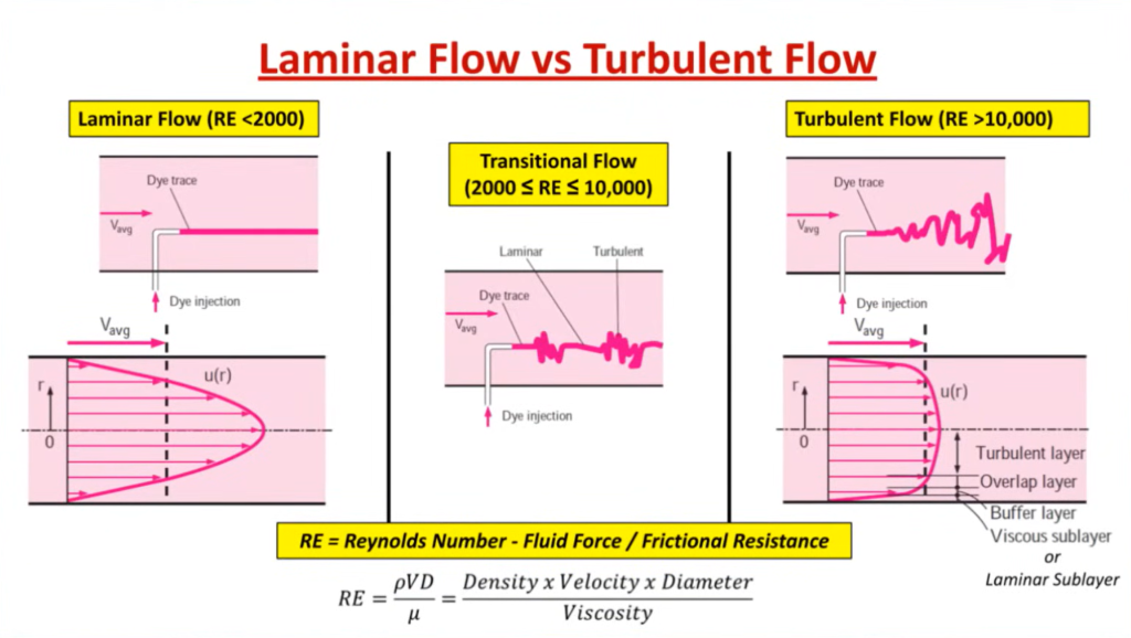
There is also a type of flow somewhere between laminar and turbulent flow, which is called transitional flow. We rarely see that in the ductwork; we’re almost exclusively dealing with turbulent flow (technically). Even if you do the absolute most deliberate duct design in the world, you won’t achieve true laminar flow.
It’s also worth noting that these flow terms (and even the Reynolds numbers) apply to any fluid, not just air. We could use it to describe the movement of water or oil in pipes as well.
Laminar vs. Fully Developed Flow
In the strict scientific sense, true laminar flow is not achievable in HVAC ducts. However, we do want to aim for an even velocity profile or more uniform flow in the ductwork, and that’s what we call “fully developed.” Fully developed flow is what keeps the ductwork filled and minimizes airflow separation, which makes it easier to measure, easier to control, and more predictable in terms of design and analysis. In low-velocity laminar flow scenarios, fully developed flow can take up to 100 times the diameter length to be achieved, as compared to turbulent flow, which can take up to 10 times the diameter length.
Duct runs in residential systems are typically too short to achieve a fully developed flow, but turbulent flow makes it easier to attain this. However, more uniform flow is usually beneficial at the grilles and over filters. We can achieve that smoother flow by using rounder, more gradual elbows wherever possible (as opposed to sharp 90s). Rounder, more gradual elbows will minimize non-uniformity, which will keep the pressure losses lower, so the blower motor doesn’t need to work as hard.
So, what does this all mean for the average contractor? Hypothetically you COULD have a duct that would be so large, and the flow would be so laminar it would shoot straight down the middle of the duct and not flow out of the takeoffs or collars, causing air distribution problems. However, the duct sizes needed to achieve this type of problem are massive and rarely encountered.
Manual J and the Trend Toward Larger Ducts
Because Manual J and our traditional duct diameters are not precise, the ACCA Manuals will point us to slightly larger ducts than what would be “perfect” in terms of the load calculation. Our ducts will almost always be slightly off.
However, total duct losses are typically only 12–16% of the entire load of a house at maximum. When our ducts are only a little bigger than what the ACCA Manuals recommend, the biggest problem will be leakage, not conduction losses. We shouldn’t worry about minimal effects from increased duct surface area and conduction losses when we have other potential issues that can impact the occupants’ comfort a lot more.
Russ King puts it best:
“We shouldn’t be splitting hairs when our job is to shave heads.”
Going up a single duct size shouldn’t cause many problems. The static pressure will be lower, and the duct system will usually get air to where it needs to go just fine. When we deliberately go up multiple sizes, we’re more likely to have enough conduction losses that’ll make an impact.
It would also help us to keep in mind that we won’t truly know how a duct design will interact with the load until we assemble it and see it in action. As you continue doing duct designs, you’ll get a sense of how they’ll behave in practice, and you’ll place less emphasis on the ACCA manuals and more emphasis on your experience during the design process.
Manual D Considerations
Manual D helps you design ducts in accordance with your load calculations. As said earlier, it will recommend bigger ducts whenever you’re between diameters. (Even if your load calculation reveals that you need a 6.1-inch duct, Manual D will recommend 7-inch ducts.)
That said, YOU are the designer and have the last word, not the manual. Manual D just puts forth some guidelines based on averages and common issues (such as noise). If it seems appropriate to bump the feet per minute in trunks to 1000, then that’s up to you. Manual D ultimately determines the critical path Friction Rate (FR) for your duct system as you make the calls.
Manual D doesn’t necessarily create a balanced design, nor does the equal or variable friction rate sizing method create equal pressure drops in all the branches. Manual D doesn’t necessarily help you create a balanced design. For example, it could lead you to install a 700-CFM trunk with two branches that split off into 300-CFM and 400-CFM runs using the same-sized duct. You might consider changing the duct sizes to even out the velocities, even if Manual D doesn’t recommend that, just to achieve that balance.
Manual D Numbers
Manual D assumes 0.08 FR and 900 fpm supply fitting velocities and 700 fpm return fitting velocities.
Some ducts with higher air velocities will have longer equivalent lengths and potential noise issues, and ducts with lower air velocities will have lower equivalent lengths. Manual D provides a conservative approach for typical residential low-pressure designs. However, using Manual D for high-pressure/high-velocity systems (i.e., large exhausts, high velocity) or very low-pressure systems (i.e., 0.20” w.c. ducted mini air handlers) will result in significant errors in diameter sizes, and therefore, the designer must revert to using duct velocities and fitting flow coefficients for sizing ducts within the allowable external fan pressure.
Friction Rate
When you’re designing ducts, you will have to determine your friction rate (pressure drop IWC per 100 feet of duct) based on the available static pressure (ASP) and the total equivalent length (TEL) of the fittings. The ASP is the remaining total pressure after we account for pressure drops in the airstream, such as across components (component pressure losses or CPLs).
It is worth noting that the TEL values in Manual D are for 900 feet per minute. The TEL will differ a little at lower or higher velocities, but it’s not like the TEL will double.
Since we’re measuring the pressure drop per 100 feet of ductwork, the friction rate equation is as follows:

The friction rate will be based on the ASP (x100)-to-TEL ratio. Manual D offers a recommended range of friction rates from 0.06 to 0.18. You can see that friction rate chart (also known as the ACCA Wedge) below. The ACCA wedge is applicable only for the Manual D sizing method. Outside the wedge can result in significant duct sizing error, as previously discussed (FR>0.18 are high-velocity high-pressure systems, and FR<0.06 are the low-velocity low-pressure systems).
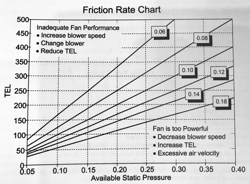
A common friction rate rule of thumb is 0.10, but it’s something we should really calculate. Larger friction rates come from having more available static and lower TELs, meaning the go-to move is to use smaller ducts. If we assume the friction rate rather than calculate it, we could end up undersizing the ductwork for the actual velocity, available static pressure, and equivalent lengths.
In cases where you have very few fittings, meaning you’ll have low TEL and high available static (high friction rate), you’re better off sizing down based on the velocity. Otherwise, the system could be noisy. It’s also worth noting that higher friction rates may require you to have velocities over 900 feet per minute. Equivalent lengths, as shown in Manual D, are calculated for a velocity of 900 feet per minute, but there isn’t likely to be extreme variation if you have a higher velocity (like 1100 feet per minute).
Tony Amadio recommends using the Manual D method for determining the friction rate but suggests using 0.08 for Manual D friction rate values > 0.08, for this can better aid in a more balanced duct design (more even branch supply velocities). When Manual D provides a friction rate lower than 0.08, then Tony will use that same lower friction rate value on just about every duct.
A Quick Word on Airflow Targets
As with anything related to ductwork, perfect is the enemy of the good. The airflow targets we shoot for vary throughout the day, so creating a duct design to deliver the perfect CFM of air to a room to maintain a specific temperature all day, every day is a futile exercise.
That’s especially true when we have varying lengths of duct runs. Conductive losses in the duct are greater with longer ducts, and it will naturally take longer for the rooms attached to those longer ducts to reach temperature than those attached to shorter ducts.
Your load calculation (Manual J) and equipment sizing (Manual S) will also have a huge impact. Longer runtimes will help the HVAC system compensate for shortcomings of the ductwork. We want to avoid short-cycling as much as possible, and an oversized appliance will run shorter cycles and make the problems associated with very duct lengths worse.
Occupants are also unlikely to complain about airflow rates that are a bit below the target; being 20% low is very different from being 60% low. The name of the game is to shoot for good airflow without getting bogged down by the details and perfectionism.
Conclusion
Manual D tends to point us to bigger ducts whenever we’re in between duct sizes, and it’s typically reliable. As long as you don’t take it too far and put 10” ducts in bathrooms, it’s pretty hard to find much of an issue with ducts that are a bit on the big side. The potential problems, such as increased duct load and velocities that are too low for proper mixing and throw, are simply not significant except in the most extreme cases.
Ducts that are too small are usually far more likely to cause comfort issues for the occupants. Load calculation, proper air distribution, and proper equipment sizing are going to be the real keys to comfort. There are some losses that come with using bigger ducts, but those have a minimal effect compared to poor load calculation or duct design.
 Related Tech Tips


Comments
To leave a comment, you need to log in.
Log In