
Get Tech Tips
Subscribe to get free tech tips.
What Airflow Goes Around HAS to Come Around

Have you ever woken up early on a Saturday morning and thought to yourself, “I really wish I knew how to size transfer grilles and jumper ducts properly?” I know I have. Although come to think of it, I believe it was a Friday morning.
Properly sizing transfer grilles is something I have been wanting to understand for a long time. ACCA’s Manual D doesn’t go into much detail, but then again, I never spent the time to dive into it.
ACCA’s Manual D Methods
Door Undercuts: Let’s start off with a “tried and true” method, door undercuts. ACCA created table N3-2 in section 4 of Manual D, which is an awesome reference that you can use to see how much return air you will achieve by an undercut alone.
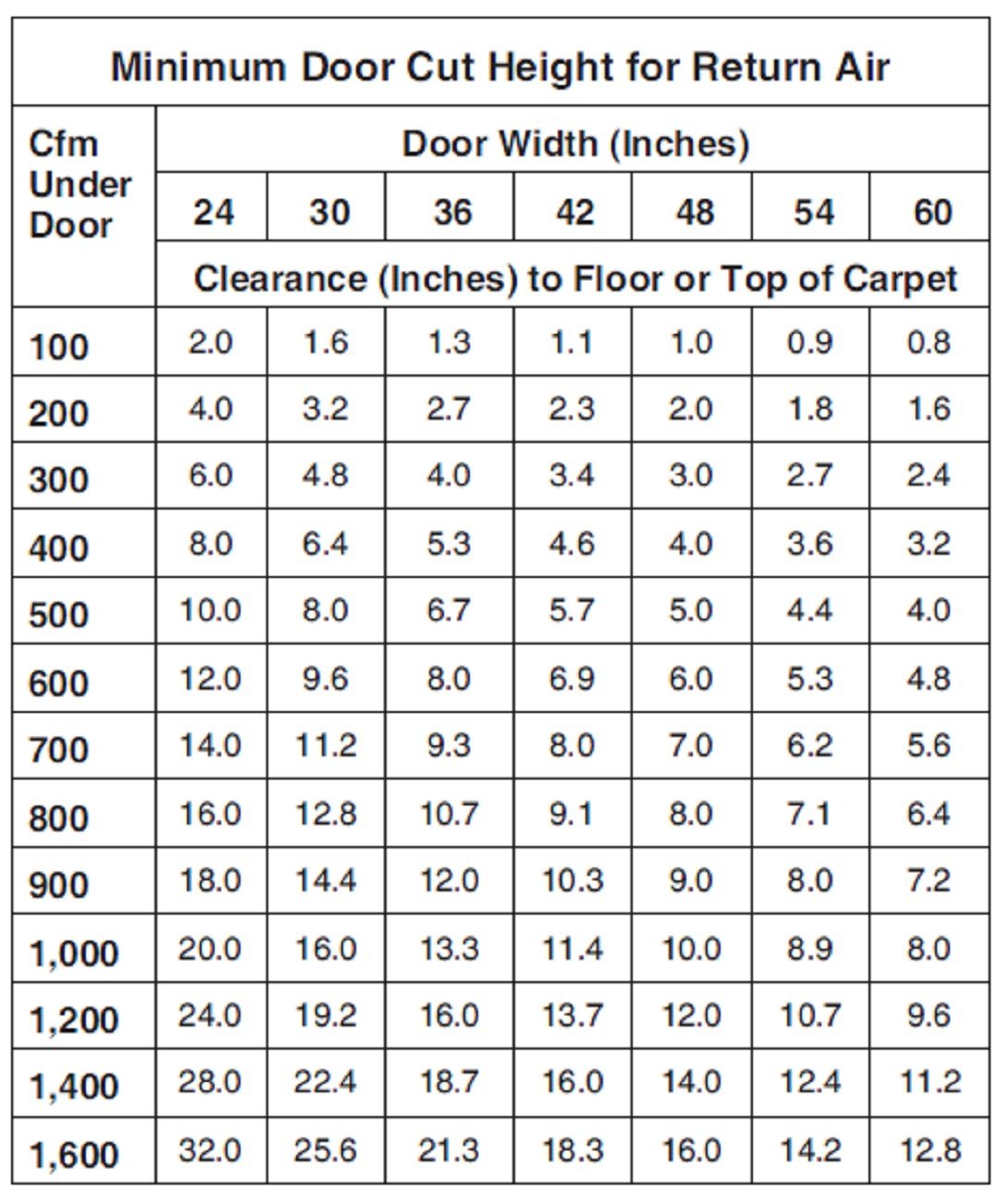
So, for a typical bedroom with a door width of 30 to 32 inches wide and a 1-inch undercut (I can extrapolate from the above table since it is linear), which is the clearance between the bottom of the door and the finished floor, I should have a low-resistance pathway and will not need a ducted return for a room supply of 60 – 70 CFM. For room supply or total room supply (think of a master bedroom with supply air not just the bedroom, but also the bathroom and walk-in closet) CFM values exceeding 70 CFM, I must add an additional transfer area for a low-resistance return air pathway. Otherwise, it will have a significant impact on the bedroom supply air whenever the door is closed.
Jumper Ducts: Section N4 – Group 14 in Manual D shows ACCA’s recommendations for “transfer ducts and transfer grilles.” This concept was a bit confusing for me, but if you look at the recommendations for a “transfer duct,” it says:
Maximum A-B Pressure Drop for Assembly = 0.05 IWC
The A-B Pressure Drop for Assembly = 0.05 IWC
- Two return grilles at 0.02 IWC per grille or less (use OEM performance data and CFM for size).
- Grille frame size determines duct airway size or flex duct equivalent.
- Two 90-degree fittings or flex duct equivalent (15 feet equivalent length per fitting or less).
Let’s unpack this recommendation a bit. ACCA recommends designing for a maximum pressure drop of 0.05” for the total jumper duct assembly. Pretend that we have a room that requires 200 CFM of return air (assume no undercut, so no additional CFM relief). The image below shows a Hart and Cooley 672 return grille, which is what we will use for this example.
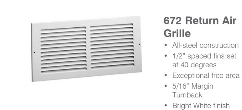
First, I found the manufacturer's performance data that listed the pressure drops at different airflows. Per ACCA’s guidelines, we must select a size with a 0.02 IWC pressure drop or less. According to the chart below, the smallest size that will work for this model grille is 12”x12”.

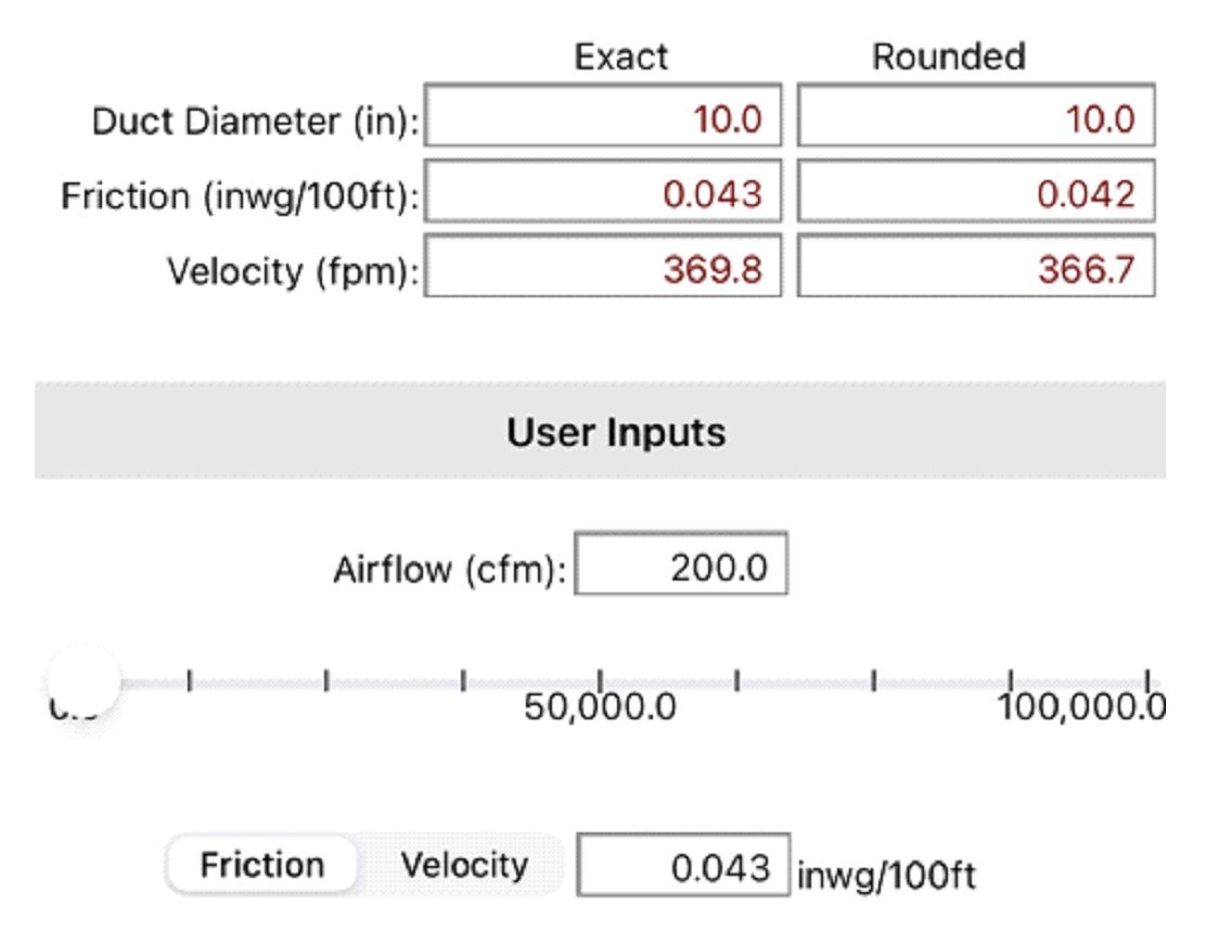
So now that I have selected the grille size, I need to figure out the duct size. ACCA says, “Grille frame size determines duct airway size or flex duct equivalent.” This statement seems rather vague to me, but let's try a 10” flex duct and see what happens.
I plugged 200 CFM into the ASHRAE HVAC Duct Sizer App and used flex duct material at a 10” diameter. After doing so, I noted the friction rate of 0.043 IWC / 100 ft and a duct velocity of 367 FPM.
ACCA’s final step is to select a boot that has 15’ of equivalent length per fitting or less. I found the boot below in Section N4 – Group 6 in Manual D. It has an EL of 10’, which is the closest match I could find.
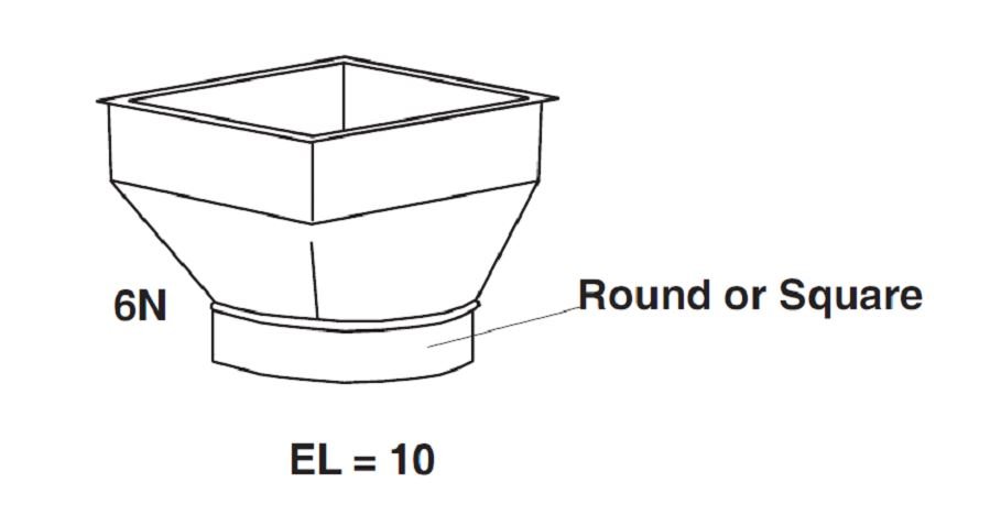
It looks like the jumper duct assembly will be 2 – 12” x 12” straight boots with a 10” flex duct jumper and using the Hart and Cooley model 672 return grille, but do not forget the two 90-degree flex elbows, each at 5 ft (Group 11 for 400 fpm flex duct velocity).
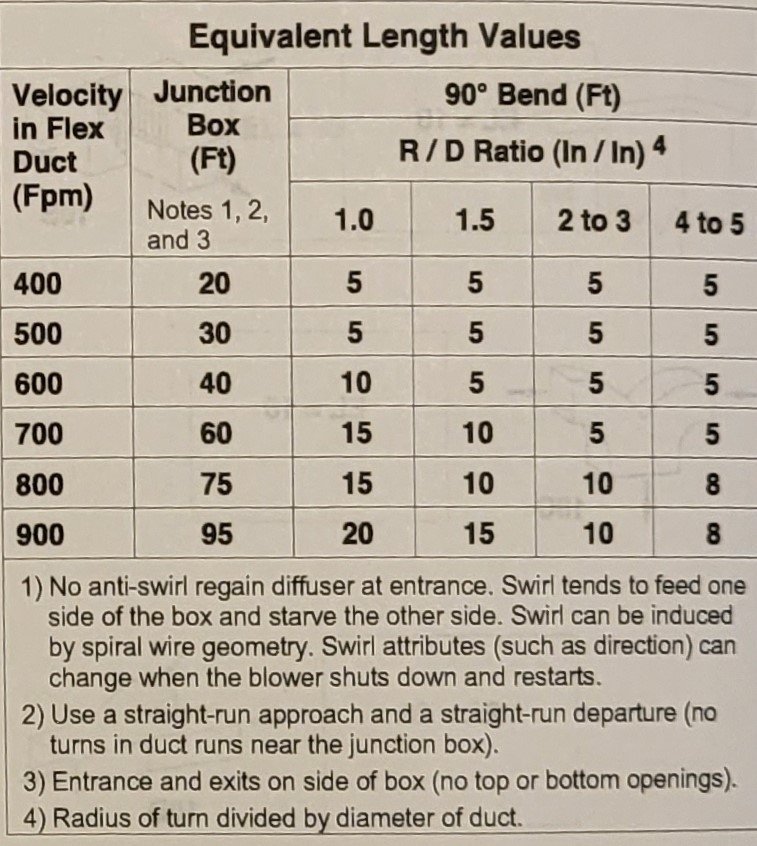
So I have two 0.02 IWC grilles for a total grille loss of 0.04 IWC. And I have a TEL of the boots and jumper flex = 10’ EL entry boot + 5’ elbow + 10’ flex length + 5’ elbow + 10’ exit boot = 40’ TEL, which gives me a pressure loss of 40 TEL x FR = 40 x 0.043 / 100 = 0.02 IWC, which gives me a total of 0.06 IWC pressure loss for this size jumper. I followed the steps, but I am actually exceeding the Manual D limit. I would have to increase the size of the registers, increase the flex duct size, or reduce the TEL of the assembly.
Instead of using the EL/TEL method of Manual D, I can go back to the Flow Coefficient Method C per the Manual Q or ASHRAE Duct Fitting Database. I go into more detail on these steps in my article “Does Your Kitchen Exhaust Suck”.
For a single duct of the same velocity, my total K of the boots/transitions and elbows K is:
C total = C boot + C elbow + C elbow + C boot = 0.98 + 0.26 + 0.30 + 0.98 = 2.52
My total pressure drop is = 0.0063 + C total VP + 10FR/100 0.0063 = 0.0126 + 2.52(187/4005) 2 + 10(0.007/100) = 0.0126 + 0.0055 + 0.0007= 0.019. But to be fair, the 14.1” should have probably been rounded up to a 16” diameter, and then I would use an 18”x18” transfer grille. Repeating all of the prior steps, we are looking at 0.007 pressure loss with 200 CFM. If I use 196 CFM, that’s a perfect 14” flex diameter, 0.018” IWC.
Transfer Grilles: Regarding transfer grilles, ACCA gives this guidance in Manual D:
Maximum A-B Pressure Drop for Assembly = 0.05 IWC
The A-B pressure drop includes two return grilles at 0.025 IWC per grille or less.
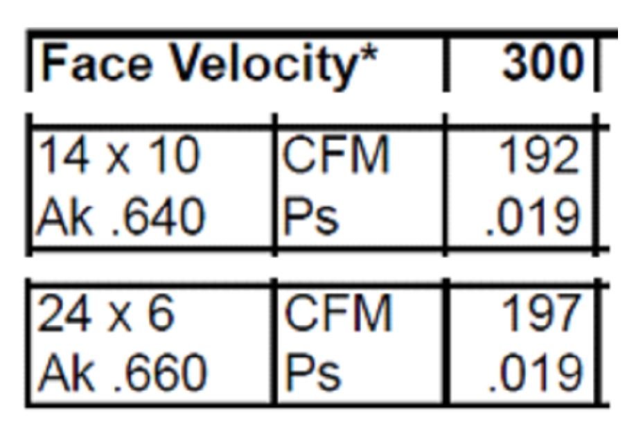
This process is much more straightforward than figuring out a jumper duct size. However, much of my return grille pressure charts provide me with sizes and CFM at values of 0.02 IWC and 0.035 IWC. It would be painful to find an exact match for 200 CFM at 0.025 IWC and would also require interpolating, so the easiest way would just be to accept the 12″x12″ or equivalent rectangular size (144 = W x H). That way, I can use, for example, a 24″ x 6″ or 14″ x 10″ above the door and accept the 0.04 IWC.
Passive house institute U.S. (PHIUS) and Energy Star homes both require room pressure to be < 3 Pascals. 3 Pa is the same as 0.01 IWC, which is 1/5th of ACCA’s allowable pressure drop.
Energy Star
The following information was taken from “ENERGY STAR” Qualified Homes – HVAC SYSTEM QUALITY INSTALLATION RATER CHECKLIST – EPA. The following recommendations help to ensure 3 Pascals or 0.01 IWC of room pressurization.
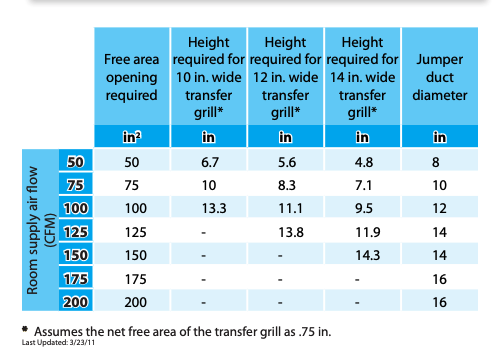
Door Undercuts: As you can see from the table below, Energy Star allows for half of the CFM through an undercut as compared to ACCA.
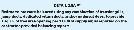
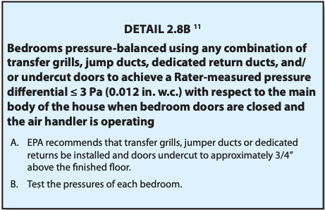
Transfer Grille: Energy Star gives this guidance for sizing a transfer grille in the table below.
Paul’s Methods
I found another resource in the Residential Ventilation Handbook by Paul H. Raymer. Let’s look at how he calculates similar return paths.
Door Undercuts: The math that Paul shows to calculate an undercut matches ACCA’s chart almost to a T. Remembering the math might be easier than carrying around a chart in your lunchbox. And better yet, it tells me this sizing formula has a 0.01 IWC drop ( 3 Pascals).
Undercut CFM = 2 x Door Slot Opening (sq in)
If all interior doors follow the guideline of 1-unch undercut clearance above the finished floor, then we can simply restate the Undercut CFM formula as:
1-Inch Undercut CFM = 2 x Door Width (inches)
For instance, we have a 5’ interior double door (60” total width) to a home office with a 1” undercut. That will allow me up to 120 CFM of a low resistance return air pathway that I do not have to return duct into that space.
Jumper Ducts: Paul Raymer uses a method developed by the Florida Solar Energy Center:
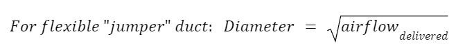
Let’s go back to our 200 CFM example
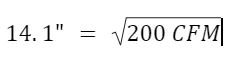
Let’s call this 14” diameter, which gives me a FR = 0.007 and a velocity of 187 FPM. Assuming the same TEL = 40’, my boot and duct resistance is now 40 x 0.007 / 100 = 0.0028 IWC.
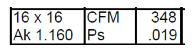
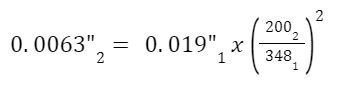
The grille sizes will now be 16″x16″, with a 0.019 pressure drop at 348 CFM. However, I have 200 CFM entering the transfer grilles. Using Fan Law 2, we can calculate what the pressure drop will be at our actual airflow.
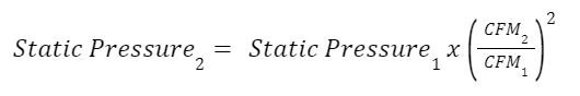
The rated pressure loss thru one return grille is 0.019 IWC. So the formula would look like this:
Therefore, my total pressure loss of the jumper is 0.0063 + 0.0028 + 0.0063 = 0.0154 IWC. This is equivalent to 3.8 Pascals, which is much less resistance than the Manual D example. However, this assumes my EL values, which are based on 700-900 FPM velocities, are correct.
Transfer Grilles: Here is the method for sizing transfer grilles shown in Paul’s book:
So if we want to figure out what grille size we would need for 200 CFM, it would look like this:
240 sq. inches = 200 CFM/0.83
Now, if I take the 240 sq. inches and divide that by a desired grille height, we will get the grille width.
240 sq. inches / 8” height = 30” width
Compare this to the Hart & Cooley 30” x 8” size at 327 CFM, having a 0.019 IWC pressure drop. We use the same Fan Law as last time to see that we would have a 0.007 pressure drop for one grille.
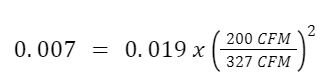
Or
0.007 x 2 = 0.014 IWC pressure drop for both grilles
What is evident in all these transfer grille sizing calculations is that the resistance is dominated by the grille resistance and very little due to the jumper duct. There are return grilles that have half the pressure drop because they have a lower fin angle and larger free area. Raymer's calculations are conservative, but the Manual D calculations still exceed 0.01 IWC drops.
Bonus Material: On page 16 of “Pressure Balancing A House & “MAD-AIR”, John Tooley describes how to make a door template to calculate the free area or hole size for pressure balancing and zone leakage issues. This is a great article, and it is definitely worth taking a few minutes to give it a read.
Keep in mind
One thing that you need to know is that these methods are additive. You can take credit for the door undercut and deduct that from your required transfer grille or jumper duct size. So if you have 48 CFM of air moving through the undercut, you would take that off of your total; 100 CFM – 48 CFM would leave you with 52 CFM of airflow to move through a jumper duct or transfer grille. However, I would be cautious of relying on a door undercut since this is something that we (HVAC extraordinaires) don’t have control over. It is a reasonable assumption to think that the door might end up with a different undercut than what you designed for.
Room pressurization issues can be a big deal and a source of many comfort complaints. If you remember one thing for this tech tip, it should be 1 CFM in = 1 CFM out. The fun part is figuring out how to make it happen.
-Adam Mufich
 Related Tech Tips


Comments
To leave a comment, you need to log in.
Log In