Mechanical Temperature Control Basics w/ Danfoss KPU 19
August 29, 2018


When unboxing a mechanical temperature control like the KPU 19, handle the components carefully, as there is a sensing bulb with refrigerant inside. Cracking the bulb will break the control. The bulb contains the vast majority of the refrigerant, but the capillary tubing can also pick up temperatures and cause the controller to read those; when possible, keep the tubing away from particularly hot areas.
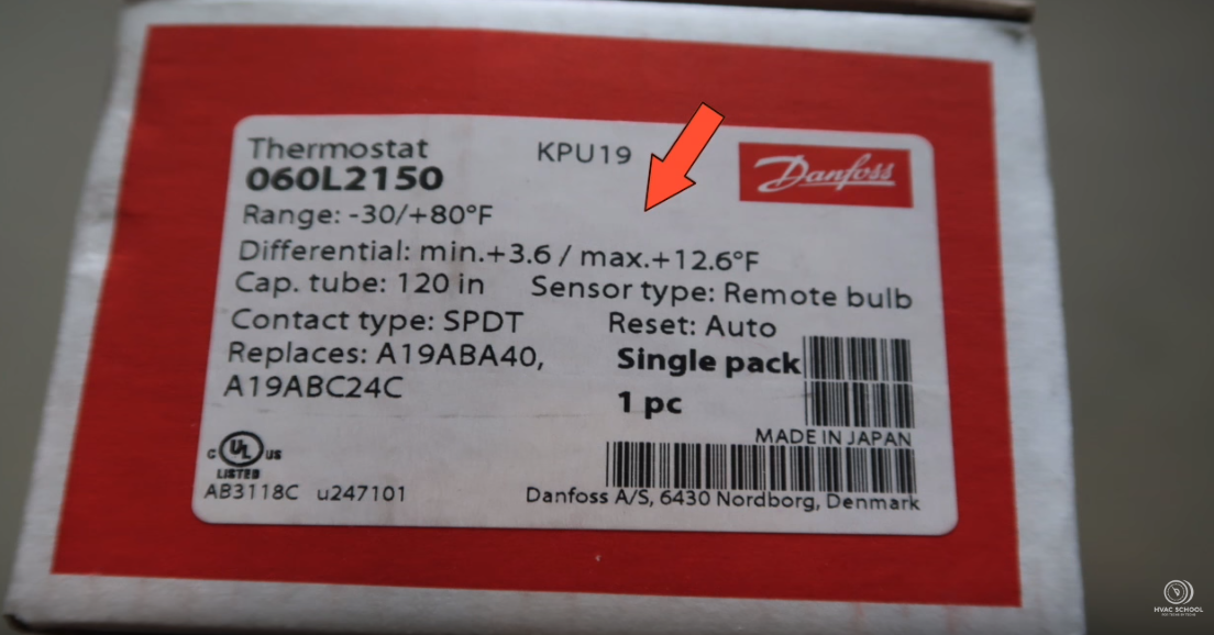
The KPU 19’s specs show that it has a remote bulb sensor, 120″ cap tube, and single-pole, double-throw (SPDT) contacts. There are three different KPU 19 models: single-pole, double-throw (SPDT) with a sensing bulb; single-pole, single-throw (SPST); and SPDT without a bulb.
When using the SPDT model with a sensing bulb for refrigeration applications, the H terminal must be connected to the C terminal (it will shut off once the box gets to temperature). The L terminal will make once the temperature drops. On the other hand, the SPST opens on low.
The KPU 19’s components include the capillary tube, conduit rubber, differential temperature adjustment valve, and mounting holes.
We use an ice bath for calibrating our thermometers, and we do the same for testing the KPU 19 by inserting the bulb into the ice bath. The temperature may read a little bit high, as the capillary tube can’t fit into the ice bath.
The arrow on the dial points to the temperature at which the control changes. Using alligator clips, we connect to the common and low-temperature sets of contacts. Since the temperature is warmer than the actual setpoint, we should see the KPU 19 cut in. The control cut in at around 32 degrees and cut out at 38 degrees. Adjusting the differential temperature valve can increase the cutout. After adjusting that valve, the control cut in at 28 degrees and cut out around 38-40 degrees.
Comments
To leave a comment, you need to log in.
Log In