Electrical Circuit Basics Part 3 – Resistance and Loads
May 4, 2018


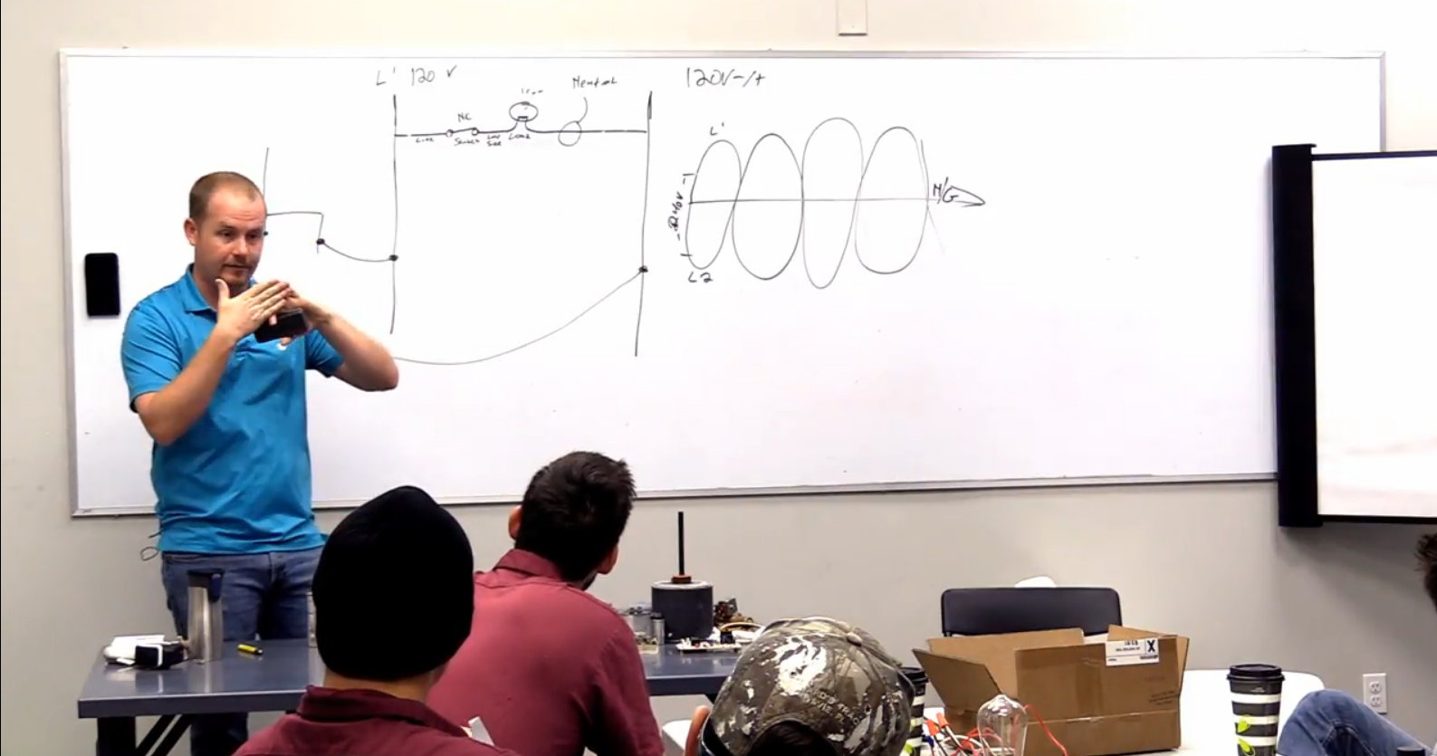
A load technically doesn’t separate the circuit, but it adds resistance; if you take a voltmeter and put one meter lead on one side of the load and the other lead on the other, you will get a value above 0 volts. On a 120v circuit, you would read 120 volts. That’s because voltage measures the potential difference between two different points on a circuit. The load also controls the flow of electrons.
However, if you read voltage between two adjacent points without any loads or separation, you will get 0. A voltage reading across a closed switch will also (usually) equal 0; a closed switch is just a path and doesn’t add resistance. However, in the case of rollout switches with carbon buildup or pitted contactors, you can see small, undesigned loads start to form on the switches or contactors.
Higher resistance equals lower amperage; more resistance impedes the flow of electrons, so fewer electrons move.
When you connect a load to a circuit, you need to put it in a place where there are differential charges on each side. In other words, a load can’t connect to and from L1; it must connect from L1 and to L2 because there are differences in charges in play.
When you read across an open switch, you will get the total applied voltage so long as the rest of the circuit is intact. (If there were two open switches, then you would read 0 because the rest of the circuit is not intact.)
Assuming that the switch is closed, you would also get the total applied voltage of the circuit if you were to read between two different sides of the load. (However, when the switch is open and you read between two different sides of the load, you would read 0 because the electrons cannot reach the load.) So, you can use your voltmeter by keeping one lead on a known opposite and “walking” the other meter lead through the circuit until you can pinpoint where the switch is open.
Comments
To leave a comment, you need to log in.
Log In