
Get Tech Tips
Subscribe to get free tech tips.
Under Pressure

A few weeks ago, I was hired to consult on a multi-family new construction project. The building was already framed, and the ducts were roughed in. The owner of the building was concerned with the quality of the ductwork. He noticed that the HVAC company was not following the mechanical engineer's plans.
This was my first time evaluating a system that wasn’t fully installed. I frequently analyze existing residential systems and recommend sizing and duct modifications. I recently wrote an article for High-Performance HVAC Today titled “Get Your Customers’ Ducts in a Row,” describing part of my process. Figuring out the issues of an HVAC system that isn’t complete was a new endeavor for me, and at first, I was a bit apprehensive. Fixing an existing system is one thing since you usually have a functioning blower motor where static pressure and airflow can be measured. I was anxious about not being able to use the fancy math I had learned over the past few years.
Long story long, let’s dive into it. With residential design, you always start with a load calc. I skipped this step since an engineer did the work for me. He was also nice enough to provide me with the equipment selected for each unit. I was able to take this information and reverse engineer the duct design.
Just The Facts
- The furnace is a Goodman GM9S920403A
- The Evaporator coil is a Goodman CAPFA3022A6
- Design Airflow is 1,000 CFM
- There will be a central return with a 14” x 24” filter grille
- The duct system is a 10” x 10” extended plenum with flex branch runs.
First, I had to calculate the friction rate to determine if the ductwork was okay. I could reference most of the pressure losses for the friction rate worksheet, but I had to solve a few of the items.
- Furnace = 0.8″ Maximum static pressure
- Evaporator = 0.454″ PD
- Filter = 0.013″ PD
- Supply Outlet = 0.03″
- Filter Grille = 0.087″
- Dampers = 2 @ 0.03″ = 0.06″
After I noted all of the component losses for the system, I deducted them from the design static pressure, like normally done on a friction rate worksheet.
(Furnace) 0.8” – (Evaporator) 0.454” – (Filter) 0.13” – (Supply Outlet) 0.03” – (Filter Grille) 0.087” – (Dampers) 0.06” = 0.039” Available Static Pressure
Cutting Our Losses
While on-site, I sketched the duct layout and quickly added up the equivalent lengths of each branch run. I came up with roughly 300’ total effective length. Let’s put it all together.
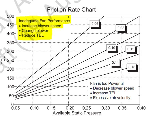
- Friction Rate = Available Static Pressure x 100/TEL
- Friction Rate = 0.039 x 100′ / 300
- Friction Rate = 0.013″
We can see the calculated friction rate of 0.013” on the Friction Rate Chart and see that it does not fall within the ACCA wedge. This red flag told me to take a longer look at everything.
Time To Slow Things Down
The next thing I looked at was the existing trunk. I questioned the friction rate that was used to end up with the 10” x 10” trunk size. When I lined up 10” x 10” on my ACCA Duct Calculator, the velocity was the first thing that jumped out at me. 1,000 CFM in a 10” x 10” duct is moving @ 1,400+ feet per minute. Returning to the fundamentals in Manual D, I know that the maximum velocity limit for a supply trunk is 900 FPM. The 900 FPM velocity is a noise thing but is also an equivalent length (EL) thing. Once you cross the 900 FPM line, all the ELs in Manual D are invalid. So, this trunk size is incorrect and should not be used.
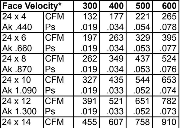
This made me want to look at the 14” x 24” filter grille listed on the plans. Manual D recommends a maximum face velocity of 300 FPM for a filter grill. I once again referenced the filter grille performance data, as shown below. As you can see, the face velocity for the 14” x 24” is 600 FPM @ 910 CFM. Since the velocity is double the maximum 300 FPM limit @ 910 CFM, it will only worsen as the airflow increases. Another red flag popped up right before our eyes. Notice a pattern?
If you have experience designing duct systems using Manual D, you might have caught a few problems early on in this tech tip. I would never recommend starting the friction rate worksheet with the absolute maximum static pressure listed on the furnace blower table. I did this to see if I could make their design work, even if it were a worst-case scenario. The other issue I noticed early on was the horrendous pressure drop of the evaporator coil. If you want a system running with decent static pressure, select components with lower pressure drops.
My Recommendations
Ultimately, I understood that I wasn’t getting paid to engineer the system from start to finish. I was there to figure out if what they did would work. My answer to the owner was no. At least not very well. And probably not for very long. They asked my advice on the easiest things that can be done to make the system work “better.” My answer was to select components with significantly fewer pressure drops, follow the velocity limits in Manual D, and use a calculated friction rate when sizing the trunk and branches.
-Adam Mufich
 Related Tech Tips


Comments
To leave a comment, you need to log in.
Log In