
Get Tech Tips
Subscribe to get free tech tips.
Solving Delta T

Delta T is the difference in temperature between two points of the same medium. It is commonly used by scientists and engineers to analyze the amount of heat transfer in a system. In general HVAC terms, it is the measurable change in temperature between an air input and air output. However, it could also be used as a diagnostic test anywhere there is a need to analyze a temperature change between two points of the same medium.

The image above illustrates one of the most common measurements of delta T. Often referred to as temperature split or evaporator temperature split, delta T can be determined by measuring the air before and after the evaporator coil and calculating the sensible change in temperature.
As technicians, we can use delta T to make assumptions about the overall working order of an HVAC system. Like most diagnostic tests, delta T should be performed with other appropriate tests to get a bigger picture. Refer to The “5 Pillars” of Residential A/C Refrigerant Circuit Diagnosis – HVAC School for a list of the fundamentals.
- Suction Pressure / Low Side
- Head Pressure / High Side
- Superheat
- Subcool
- Delta T
When used correctly, these tests will not only solve system problems but also help us develop a deeper understanding of the refrigeration cycle and equipment processes.
The problem with these types of tests is that they are often misunderstood and frequently misused. Due to the simplicity of these tests, I think we tend to abuse them and then distrust them because we perceive the results as being unreliable—when the truth is that we failed to implement proper testing procedures to begin with.
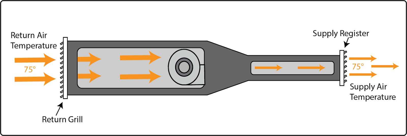
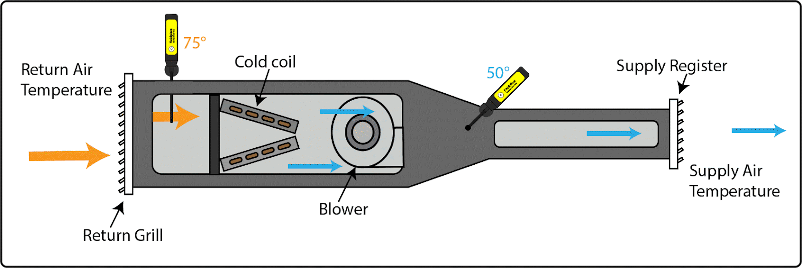
I am guilty of the practice of cutting corners, and to be honest, there were times I simply didn’t know any better. Or even worse, I acted out bad habits and methods taught by someone who didn’t really understand them either. And the delta T test is no exception. How many of you were taught to measure the air at the return grille and a supply register, subtract one from the other, and hope you have 20°F? I was!
Before research began for this article, my general method of delta T testing was always some variation of the image below.
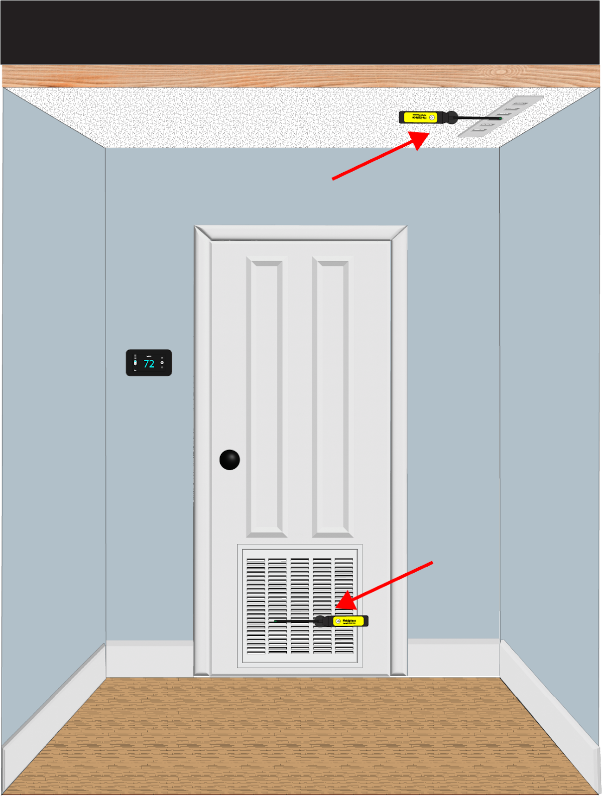
This method is technically correct, as it is, at face value, the difference in temperature between two points, which is how we define Delta T. However, it also has the potential to be flawed because a key component of Delta T testing is that we are testing two points of the same medium. So, unless you are working in houses with absolutely perfect ducts, then the medium you are testing is likely to be impacted by unwanted gains. The impact can come from improperly sealed, torn, or poorly insulated ducts—just to name a few examples. So when we are talking about evaporator Delta T or evaporator temperature split we must ensure that the air we are testing is consistent and free of unwanted gains. This is why probe placement is critical.
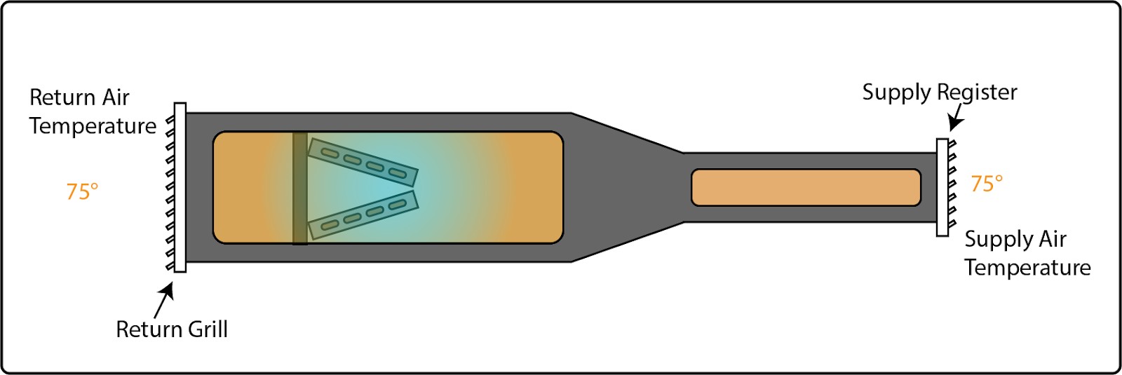
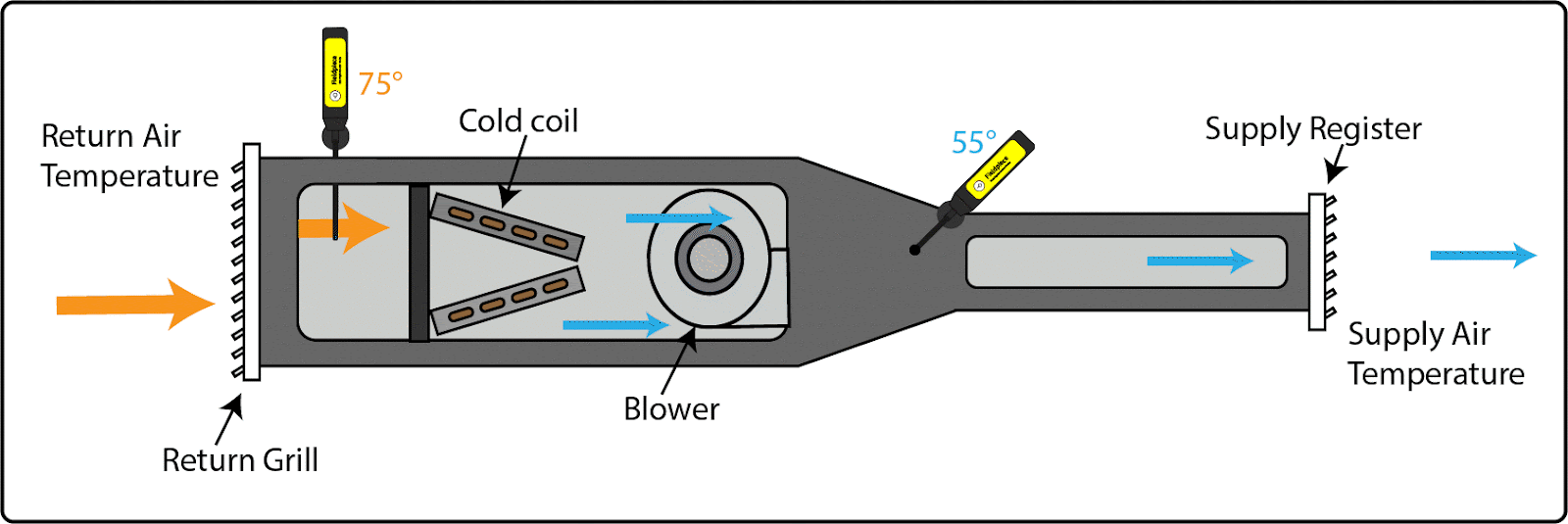
Probe Placement is Critical
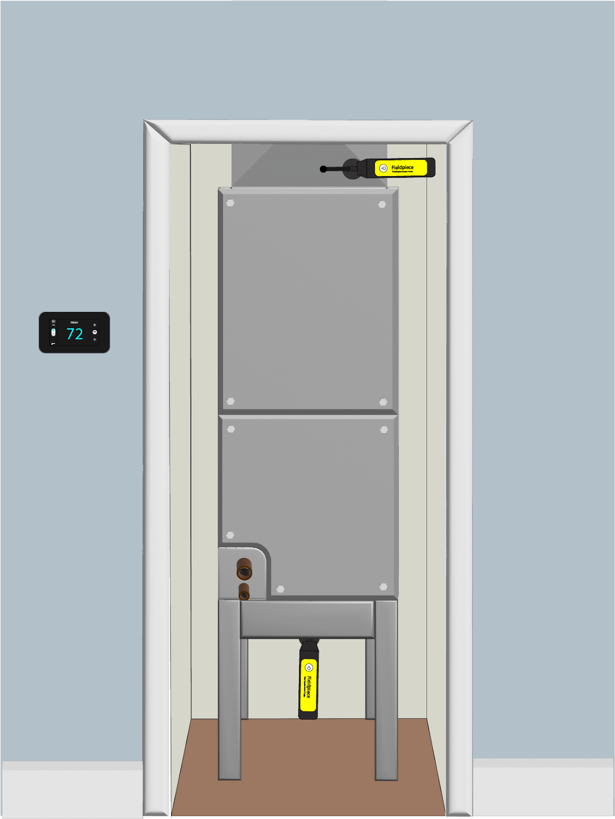
The image above represents the proper placement of temperature probes. Notice that the supply air probe is placed just above the air handling unit instead of at a supply register, limiting the possibility of unwanted gains to the air stream caused by compromised ductwork.
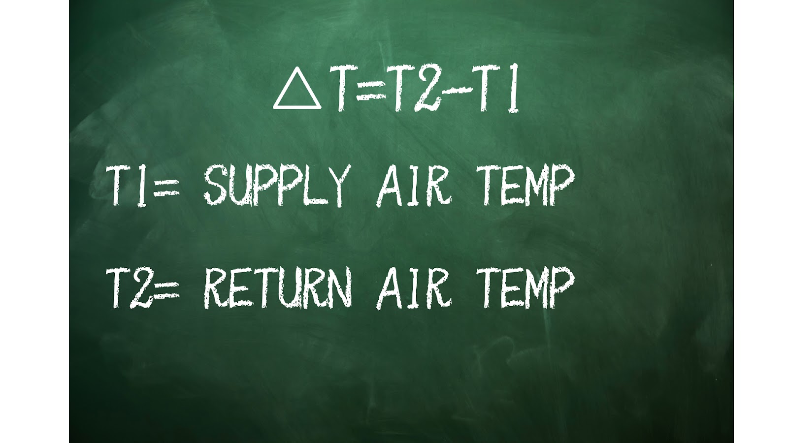
Why is it called Delta T?
Delta comes from the Greek alphabet and is represented by a ∆ triangle symbol. Delta means “change” or “difference.” The letter T stands for temperature, and the delta T equation is ∆T=T2-T1
The delta T formula is fairly simple, but like any other equation, the information you get back is only as good as the information you put in. Solid temperature measurements and proper probe placement are essential to achieve flawless measurements.
Solving Delta T
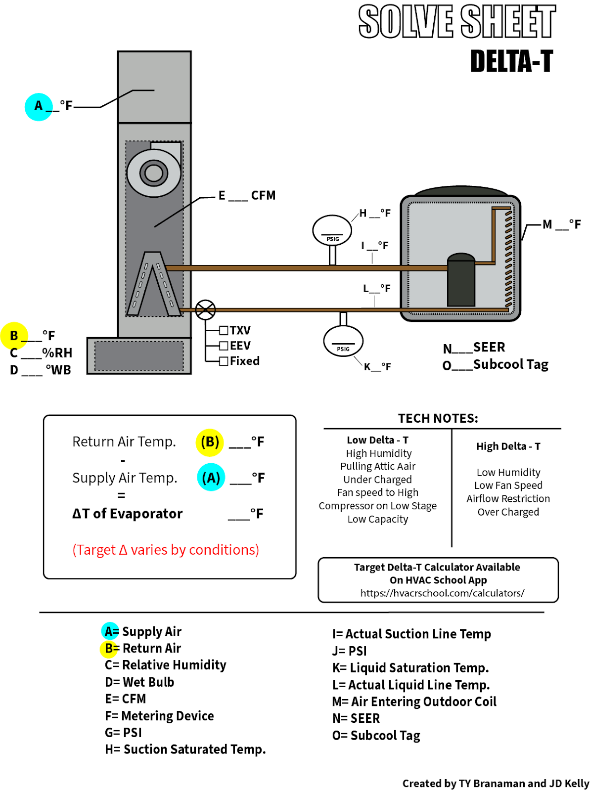
The solve sheet above is part of a series of sheets meant to help techs master the fundamentals of diagnostic testing. It will hopefully help users better understand some of the processes and procedures needed to develop the skills to be a well-rounded technician. Just like the subcool and superheat solve sheets https://hvacrschool.com/solving-superheat/, the delta T sheet will help you test and find a system’s delta T, but it doesn’t tell you what the target delta T should be. We have to dig a little deeper to find that.
What should the system’s Delta T be?
Get ready for a “rule of thumb alert.” That's right. There is no fixed temperature measurement to rely on for every piece of equipment. Manufacturers tend to vary the target delta T depending on the design of the equipment. However, there is a down-and-dirty commonly used rule of thumb of 20°F.
It is important to note that a delta T measurement is primarily a starting point of a larger investigation. It should not be solely relied upon as a de facto solution to the functionality of the overall system because it is possible to have a perfect delta T reading and the system actually be performing poorly. It is also possible to have a lower-than-expected delta T but see the system performing at adequate levels.
It has to do with conditions. Humidity, airflow, load, etc., all of which affect delta T.
However, most equipment does have a specific delta T associated with it defined by the manufacturer. It just so happens that the majority of equipment falls into the 16–20°F range, but the designed delta T can often be found in manufacturers’ literature. There are also some target delta T sheets like the one below that are based on the return air wet and dry bulb temperatures.
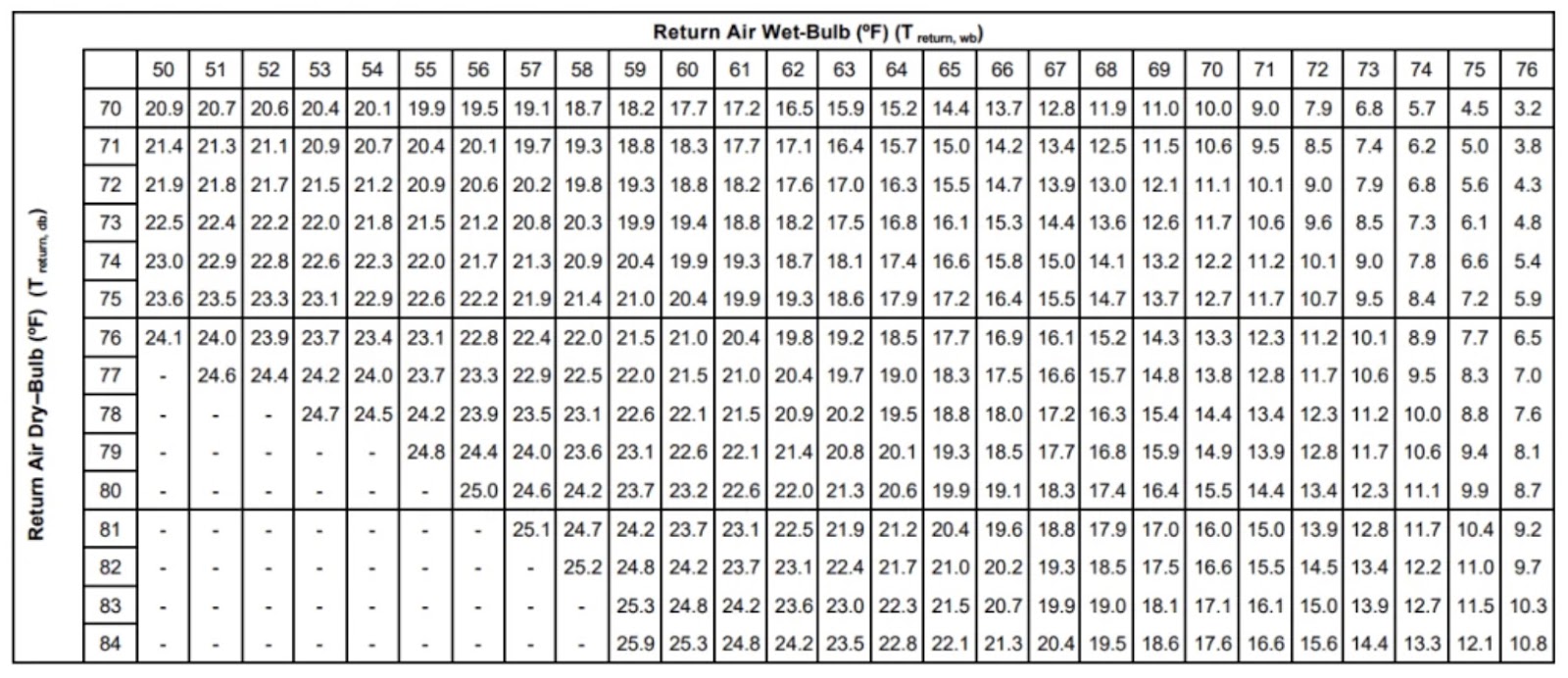
Or you could use the delta T calculator found on the HVACR School website https://hvacrschool.com/calculators/
These delta T targets are largely based on 400 CFM per ton system settings. However, in areas such as the Southeastern USA where humidity is high on average, technicians are finding more and more units set to operate at 350 CFM per ton. This lower fan speed setting enables the system to extract more humidity from the dwelling but renders the use of most delta T charts and calculators not applicable. Delta T readings will tend to be higher on these 350 CFM systems because the slower fan speed allows for more heat absorption by the coil.
Ty Branaman also teaches us how to calculate target delta T by using a detailed cooling capacity chart in this video https://www.youtube.com/watch?v=pPRJqDoVCXc.
At a minimum, you need to know that 20°F is just a rule of thumb to get you within reason. Depending on conditions and the equipment design, the actual target delta T can vary. Without knowing the actual target delta T, any delta T measurement lacks real meaning.
That’s because if you are only chasing a 20°F split but the system conditions call for 15°F, any adjustments you make to the system will most likely be a detriment to the system’s overall performance.
What affects a system’s delta T?
Now that we know the importance of ascertaining the target delta T, let’s move on to what could be affecting the measurement and causing us to miss our mark.
The first stop is airflow. Airflow plays a tremendous role in system performance and will directly affect our delta T. Usually, manufacturers design their systems based on 400 CFM per ton, so a deviation from this setting will affect our temperature split. Increasing the blower motor speed will cause a decrease in the split, whereas decreasing the blower speed will increase the split. This is a concept that goes straight to the heart of HVAC. It is the concept of heat transfer and one of the reasons I think that understanding delta T will help improve our overall comprehension of the refrigeration cycle.
Let’s first consider what causes the temperature split to occur in the first place. The key components are air, a fan to move the air, and a cold coil to remove heat from the air.
In scenario 1, we have only the fan and the air. Without the cold coil to absorb heat, the system merely moves air from one point to another.
In scenario 2, we have a cold coil but no fan, and what we see is that only the air surrounding the coil is cooled.
In scenario 3, we see the basic elements required to produce a temperature split.
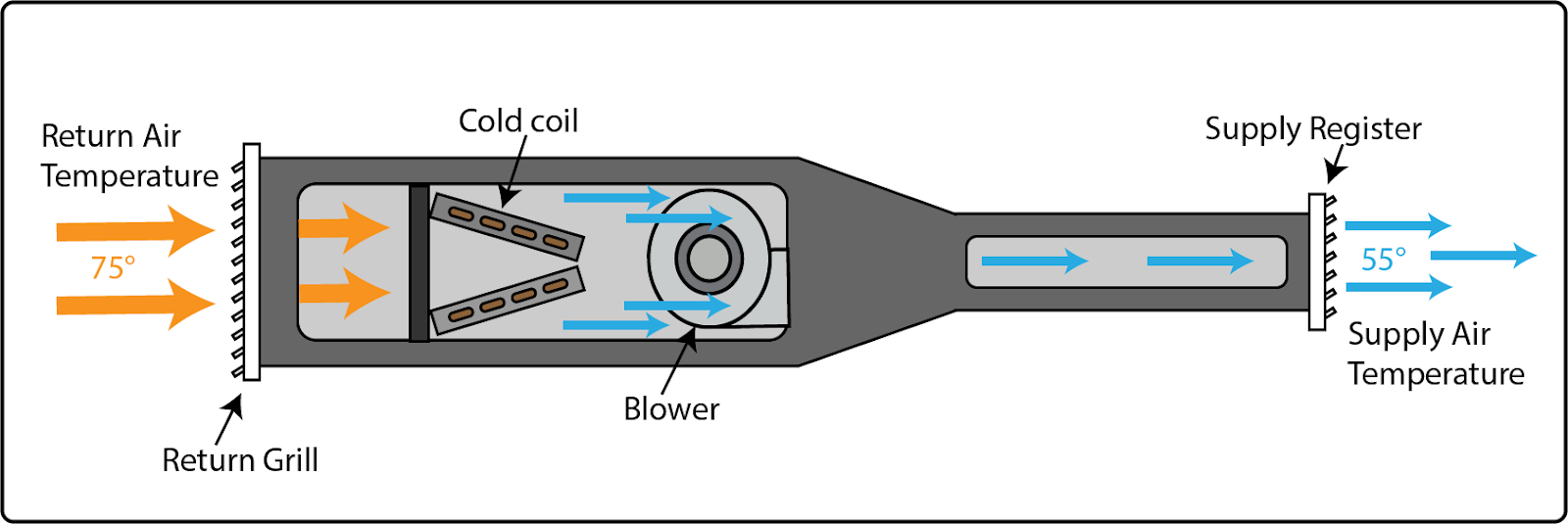
I know this seems elementary, but consider this: we know that to achieve a proper split, we need proper airflow over a properly cooled coil. These two elements of the equation are directly linked to the system's capacity. The system's capacity is its ability to absorb heat and is measured in tons, which is equivalent to 12,000 BTUs an hour.
A 3-ton system in optimal conditions will be able to absorb 36,000 BTUs per hour at 400 CFM. The available capacity doesn’t change because the airflow changes. So, altering the fan speed won’t change the capacity or the amount of heat that can be absorbed. Instead, an increase or decrease in velocity will change the amount of air passing through the coil respectively, but the BTU absorption potential of the coil remains the same.
This means that we can now predict some airflow causes and effects in relation to delta T.
We should also be able to intuitively diagnose some airflow issues affecting our temperature split. For instance, because we can now predict that increasing airflow will reduce our temperature split, we can now assume that airflow might be the cause of a low delta T. We now have a logical starting point for our system diagnostics.
Decreased Air Speed = High split
Proper Air Speed = Proper Split
Increased Air Speed = Low Split

Humidity
The scientific principles related to humidity are a bit trickier to understand. I’m not going to go into great detail here, but a quick explanation is that air high in humidity will produce a lower temperature split. Don’t worry if it sounds confusing—it is. But high humidity means that there is essentially less mass per cubic foot compared to a cubic foot of drier air. The volume remains the same, but the density changes. It sounds counterintuitive because humid air feels heavy, but water vapor molecules are lighter than air molecules. So it stands to reason that a cubic foot of humid air will be less dense than a cubic foot of dry air.
Two things cause low temperature splits when the humidity is high. The first is that there is less air available for sensible heat absorption per cubic foot because the air is less dense. The second has to do with latent heat removal and is the process of condensing moisture from the air as it passes through the coil. It takes a lot of energy to change water vapor to liquid water. The process of latent heat removal affects the sensible heat exchange over the coil, causing the temperature split to be lower than that of dry air.
Refrigerant Charge
Delta T is not a reliable test to determine if the refrigerant charge is correct. There are too many variables that could produce unreliable results, as you could be just as likely to read a 20°F split on a system that is improperly charged as you are to read 12°F on a system that is properly charged.
Load
Load can have a significant impact on temperature split. For instance, the split will be high during the initial startup of a system that has been off for a while with hot and humid conditions indoors.
Conclusion
Just like superheat or subcooling, delta T is just one piece of the diagnostic puzzle. It’s not something that we can use to get a complete idea of an HVAC system’s health, especially because it will vary with conditions like humidity and airflow.
The hard and fast 20°F rule of thumb isn’t always so. You’re better off looking through the manufacturer’s literature and using the delta T solve sheet or calculator to see how the system in front of you stacks up. And make sure your probes are in the right place—you should get your T1 reading in the supply plenum, not at the register.
—JD Kelly
 Related Tech Tips


Comments
To leave a comment, you need to log in.
Log In