
Get Tech Tips
Subscribe to free tech tips.
High-Pressure vs. Low-Pressure Shell Scrolls: A Deeper Dive

I want to share something that came up in a recent discussion with Roman Baugh about VRF systems, and it made me realize I might have had a blind spot regarding scroll compressor designs. We were talking specifics, and he brought up high-pressure shell compressors. My immediate thought was, “Hold on, aren't scrolls low-pressure shell compressors since they are refrigerant-cooled?” It turns out that while many common scrolls are low-pressure shell compressors, the high-pressure design is prevalent, especially in certain applications, and understanding the difference is key.
So, let's look at the engineering and practical implications. We'll explore the internal mechanics, the thermodynamic consequences, and what this means for us as technicians performing diagnostics and service. Think of this as translating the engineering specs into field-relevant knowledge.
Defining “High-Pressure” vs. “Low-Pressure” Shell
These terms describe the dominant pressure and thermal environment inside the compressor's external casing or shell during operation.
In a low-pressure shell (LPS) design, the compressor shell interior is predominantly at suction pressure and temperature. It effectively functions as an extension of the low-pressure side of the refrigerant circuit, containing cool suction vapor returning from the evaporator.
Conversely, in a high-pressure shell (HPS) design, the entire internal volume of the shell is maintained at discharge pressure and contains hot, superheated refrigerant gas directly after compression. The shell essentially becomes part of the high-pressure side.
Consider the internal environment: the LPS design places the motor and other components within a relatively cool, low-pressure vapor environment. The HPS design immerses these same components in a hot, high-pressure gas environment. While both are utilized in modern systems, the LPS configuration has been widely adopted in conventional HVAC for its inherent motor cooling advantages. HPS designs are often employed where factors like unit compactness or specific performance goals in applications like VRF are prioritized.
Tracing the Refrigerant Path: Internal Flow Dynamics
The critical distinction lies in how refrigerant vapor transits the compressor:
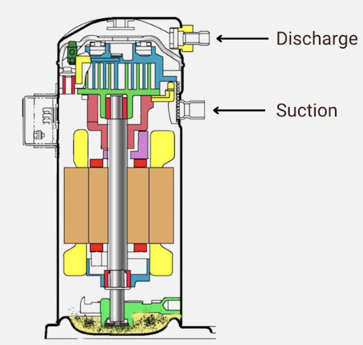
- Low-Pressure Shell (LPS / Suction-Gas Cooled): Suction vapor enters the shell, typically into a lower section. This large volume acts as a suction gas storage tank, sort of like another accumulator, allowing gas velocity to decrease, which aids in separating entrained oil droplets and minor amounts of liquid refrigerant. The cool suction gas then flows across and through the motor windings—providing direct convective cooling—before entering the scroll set for compression. The compressed, hot gas exits the scroll set, often passes through an internal discharge check valve (to prevent back-spinning at shutdown), collects in a smaller volume (often a top dome), and exits through the discharge connection. The majority of the shell's internal volume is thus maintained near suction conditions.
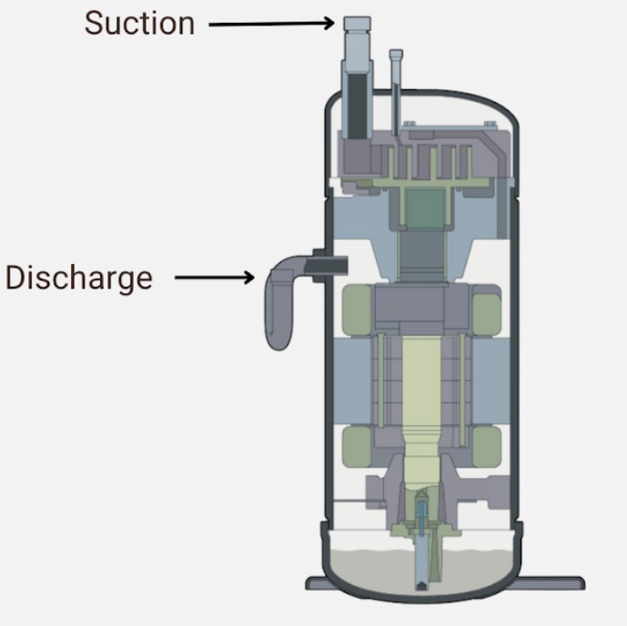
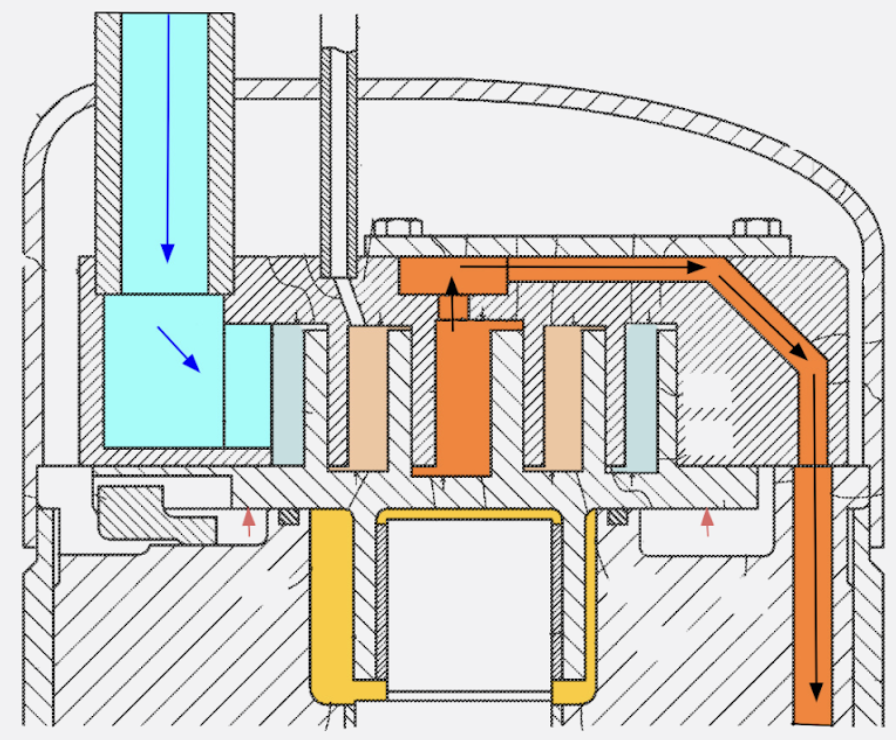
- High-Pressure Shell (HPS / Discharge-Gas Environment): Here, the flow path is substantially different. Suction vapor typically enters through a connection and is routed more directly, often via internal tubing or passages, into the inlet of the scroll set, bypassing the main shell volume. After compression, the hot discharge gas is expelled from the scroll set directly into the main shell volume, turning the entire shell into a high-pressure, high-temperature discharge plenum or muffler. The discharge line connection draws this hot gas from the shell. Consequently, the motor and scroll assembly are continuously surrounded by discharge-temperature gas.
Externally, the suction and discharge connections might appear conventional. Internally, the thermodynamic environment and flow architecture are fundamentally distinct.
Motor Cooling: A Critical Thermodynamic Difference
The method of rejecting waste heat from the electric motor windings is a major differentiator with significant reliability implications:
The LPS design utilizes the returning cool suction gas as the primary motor coolant. The entire flow of refrigerant vapor is directed over the motor windings before compression. This setup provides effective convective heat transfer, maintaining lower, more stable motor operating temperatures, which generally correlates with increased motor longevity (as motor insulation life is inversely related to operating temperature). Furthermore, the motor's heat energy is transferred to the refrigerant before compression, which can slightly improve cycle efficiency and provide a mechanism to vaporize small amounts of entrained liquid refrigerant, offering some protection against liquid slugging.
The motor resides within the hot discharge gas environment in the HPS configuration. Heat rejection from the motor windings is significantly less effective because the surrounding gas is already at a high temperature, reducing the thermal gradient for heat transfer. As a result, HPS motors inherently operate at higher winding temperatures. These higher temperatures necessitate the use of motors with higher temperature class insulation and place a premium on motor efficiency (e.g., brushless DC motors often used in inverter-driven HPS scrolls) to minimize waste heat generation. While engineered to handle these temperatures, the reduced cooling effectiveness is a key design constraint. Studies comparing the two designs often show significantly lower winding temperatures in LPS scrolls under similar load conditions.
This thermal difference is readily observable using non-invasive tools, which we'll discuss shortly.
Oil Management and Internal Pressures
Lubricant behavior and management are also strongly influenced by the shell design:
In an LPS design, the base of the shell serves as the primary oil sump, maintained at suction pressure. Oil lubricates components and returns via gravity and refrigerant flow. The low-pressure environment generally results in less forceful oil ejection during off-cycles. A portion of oil is continuously circulated as a mist entrained in the refrigerant flow. The large volume and relatively cool temperature can allow some tolerance for temporary liquid refrigerant return, as liquid refrigerant may pool in the sump and vaporize gradually. However, lubricant properties (viscosity and miscibility with refrigerant) are still critical, and chronic liquid return is still detrimental.
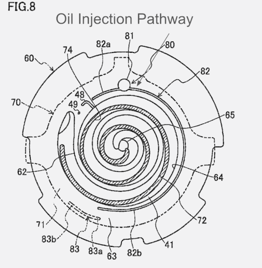
In the HPS design, the oil sump resides at discharge pressure, meaning the oil is subjected to higher temperatures and pressures, potentially increasing refrigerant solubility in the oil. This high pressure can promote oil migration out of the compressor, especially during shutdown. Consequently, HPS systems often require more sophisticated oil management strategies. This may include external oil separators or active oil return systems, such as the High-Pressure Oil Return (HiPOR™) mechanisms seen in some VRF systems, which create a dedicated path to return oil efficiently to the compressor, improving lubrication reliability and potentially system efficiency, particularly under varying load conditions or in systems with extensive piping.
Internal pressure differentials across the scroll components also differ, influencing bearing loads and sealing mechanisms (axial and radial compliance). Engineers design for these forces in both types, but the HPS environment generally imposes greater thermal stress on bearings and lubricants.
Rationale for Choosing HPS or LPS Designs
The selection involves engineering trade-offs based on application requirements:
LPS Advantages:
- Proven reliability track record in standard applications
- Superior motor cooling (leading potentially to longer motor life)
- Inherent tolerance for minor liquid return
- Simpler oil management (in many cases)
HPS Advantages:
- Potential for more compact unit design for a given capacity (valuable in space-constrained applications like VRF)
- Potentially favorable performance characteristics in high-lift or heating-dominant scenarios (hot shell resists internal condensation in cold ambient heating)
- Can be integrated effectively with advanced oil management for complex piping installations
Essentially, LPS often prioritizes robustness and proven motor cooling for general use, while HPS is often chosen for specialized applications demanding compactness or optimized performance under specific, challenging conditions, accepting the inherent thermal management challenges. As a result, the LPS design is favored by many manufacturers for conventional unitary and refrigeration systems.
Identifying the Difference: Beyond the Touch Test
Instead of relying on potentially hazardous physical contact, we can use diagnostic tools:
The first method is to use a thermal imaging camera or infrared thermometer, which is the most effective non-invasive method. A thermal camera or a spot IR thermometer will reveal distinct thermal signatures.
- An LPS scroll will typically show a shell surface temperature closer to the suction line temperature over most of its area. You might observe a gradient, with the top dome or discharge line area being significantly hotter. Condensation might be visible on the cooler parts during AC operation.
- An HPS scroll will exhibit a much more uniform and significantly higher surface temperature across the entire shell, approximating the discharge line temperature. This difference in thermal patterns is a strong indicator of the internal design.
The next method is to check the model nomenclature and documentation. Always consult the compressor's nameplate and the equipment's service literature. Manufacturers often use specific model codes or explicitly state whether the design is suction-cooled (LPS) or utilizes a high-pressure shell (HPS). This is definitive.
Finally, while not absolute, the application (system type) provides clues. Scrolls in standard residential/light commercial package units or split systems are very likely LPS. Scrolls found in VRF/VRV outdoor units, especially inverter-driven models, are frequently HPS designs.
Service and Diagnostic Considerations
While fundamental refrigeration service principles apply to both, keep these nuances in mind:
Refrigerant Mass Flow
Maintaining adequate refrigerant flow is vital for all compressors, but it's critically important for HPS types due to their reliance on refrigerant throughput for any cooling effect on the motor environment. Conditions like low charge or malfunctioning expansion valves can lead to rapid overheating in an HPS scroll.
Crankcase Heaters

Essential for LPS scrolls to prevent off-cycle refrigerant migration into the low-pressure shell and subsequent liquid dilution of oil. HPS scrolls may have different off-cycle migration dynamics, but liquid management at startup remains crucial; follow manufacturer guidance regarding heaters or pump-down controls.
Thermal Assessment
When diagnosing potential overheating (e.g., internal overload trips), use your thermal imager or IR thermometer to compare actual shell temperatures against expected norms for that specific type (LPS or HPS) under the current operating conditions. A hot LPS shell is a clear warning sign; a hot HPS shell is expected, but an excessively hot HPS shell still indicates a problem. Correlate with superheat, subcooling, pressures, and amperage.
Oil Management Systems
For HPS scrolls, particularly in VRF applications, be aware of any specialized oil return systems or control sequences. Malfunctions here can quickly lead to lubrication failures. Consult OEM procedures for verifying oil levels or diagnosing oil return issues.
Shutdown Acoustics
That brief clatter or reverse rotation sound upon shutdown in any scroll often points to a leaking internal discharge check. This allows high-pressure gas backflow, potentially causing damage over time.
Typical Failure Modes
While sharing common scroll failure mechanisms, some may be more associated with one type:
LPS failures are often linked to lubrication issues stemming from liquid refrigerant floodback (washing out oil) or oil logging elsewhere in the system starving the sump:
- Motor overheating due to loss of suction gas cooling (e.g., low charge)
- Bearing or scroll wear from contamination or poor lubrication
- Failure of the internal discharge check valve
HPS failures:
- Motor winding failure due to insulation breakdown from prolonged high-temperature operation, often exacerbated by inadequate refrigerant flow
- Bearing failures due to lubricant breakdown at high temperatures or insufficient oil return.
- High-side leaks (since the shell is high-pressure)
- Potential startup difficulties if internal pressures don't equalize correctly
Conclusion
Understanding the distinction between low-pressure and high-pressure shell scroll compressors moves beyond basic identification into appreciating the underlying engineering choices and their practical consequences. The internal thermodynamic environment dictates how the motor is cooled and how oil behaves, and it ultimately influences the compressor's operating characteristics and potential failure modes.
Recognizing whether you're working with a cool-running LPS design or a hot-running HPS design – readily distinguishable with thermal imaging – provides immediate context for your diagnostic measurements. It allows you to interpret temperatures and pressures more accurately and apply the correct service considerations.
As systems like VRF become more common, encountering HPS scrolls will be increasingly frequent. Adding this knowledge to your diagnostic toolkit enables more precise troubleshooting and effective service, ensuring the reliability of these sophisticated machines. Keep observing, keep questioning, and keep learning the science behind the systems we work on every day.
—Bryan
 Related Tech Tips


Comments
To leave a comment, you need to log in.
Log In