
Get Tech Tips
Subscribe to get free tech tips.
Electronic Expansion Valve Troubleshooting

Electronic expansion valves (or EEVs) are metering devices that you’ll find in a variety of modern HVAC equipment, including heat pumps, VRF units, inverter mini splits, and chillers. This valve is electronic rather than mechanical and can precisely control the flow of refrigerant into the evaporator and optimize efficiency for heating and cooling units.
Other manufacturers refer to these valves as LEVs—Linear Expansion Valve (Mitsubishi), EXVs—Electronic Expansion Valve (Carel), and EOSM—Electronic Operated Step Motor (Sporlan). There is a wide variety of EEVs in today’s market, but for the purpose of this tech tip, we are focusing on the most commonly found valve type in both residential and commercial equipment as it pertains to R410a systems.
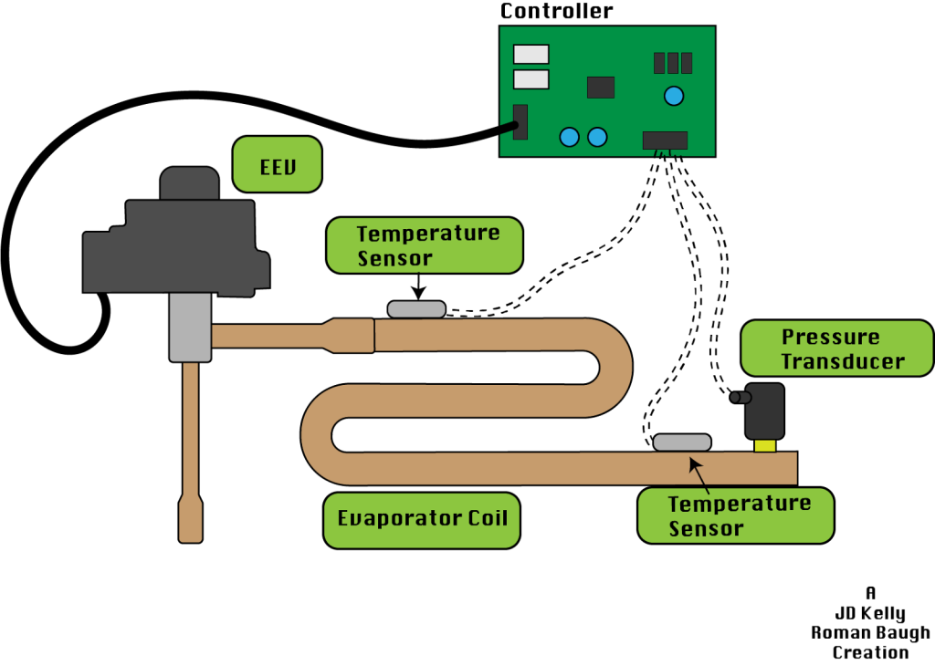
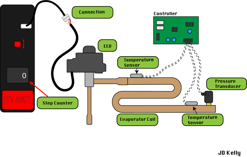
Temperature and pressure sensors are used to measure the refrigerant and calculate superheat based on the manufacturer of the equipment these valves are found within. This is then used by the controller to determine how much the valve should open or close to maintain the correct superheat based on the desired outcome the system has predetermined. Certain modes override the normal control of this valve to achieve a specific outcome for the entire system, such as Oil Return, or for safety, like Freeze Protection.
Like any other electronic or mechanical device found on HVAC equipment, the EEV can fail. Let’s take a look at some of the symptoms of a failed EEV and discuss some of the field tests to use while troubleshooting the device.
Understanding the EEV
It is important to understand the basic parts and operation of an EEV before attempting to troubleshoot the device. This is your standard 480 pulse EEV found in 95% of equipment you’ll find in the North American market.
The basic parts of the EEV consist of:
- A power head
- The valve itself
- Electromagnetic coil
- Permanent magnet
- Threaded shaft
- Needle
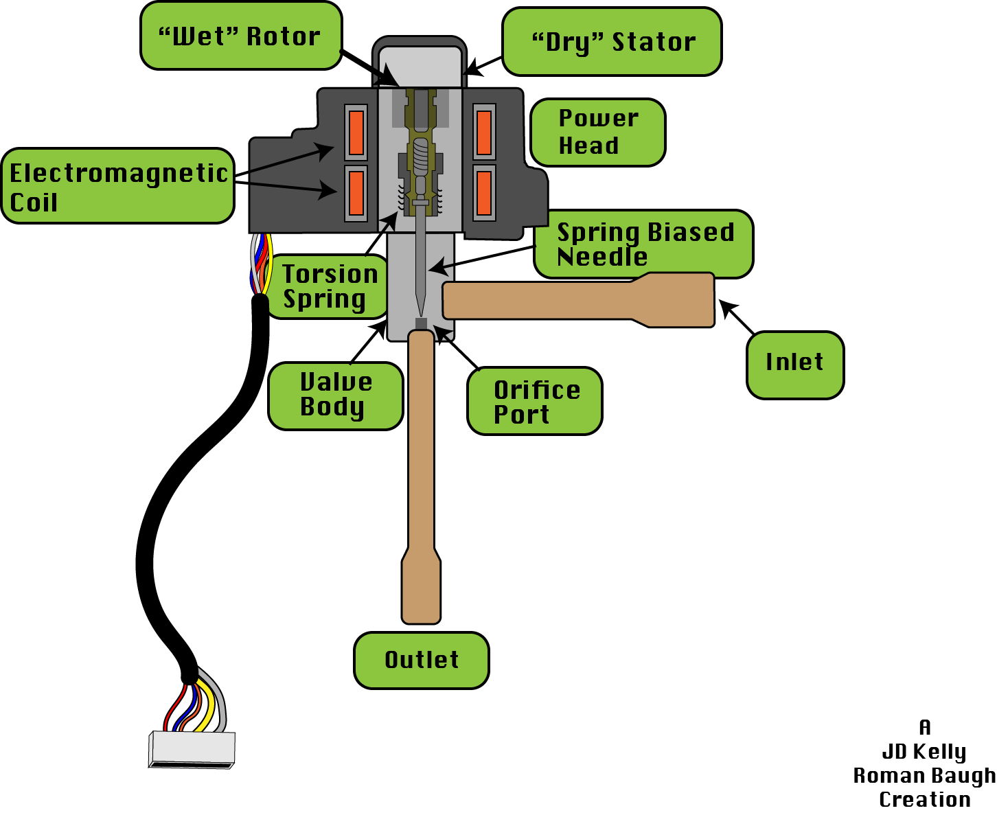
The power head is the brain of the EEV. It receives electrical signals from the controller to energize the electromagnetic coil. The electromagnetic coil energizes the offset windings in an electrical pulse pattern that grips the internal rotor of the valve through the stainless steel casing, causing the rotor to rotate and move the needle up or down. Valve “steps” are incremental changes to the rotor position. Typically there are 48 to 60 different available “steps” to control an EEV such as this.
The power head spins the permanent magnet clockwise or counterclockwise, depending on the controller’s algorithms and the system's needs. Typically, clockwise is closed, and counterclockwise is open. However, you should always read the appropriate service manual before attempting to manually operate the valve.
The permanent magnet drives a needle up or down based on superheat readings translated by the controller from the sensors. Usually, the EEV employs two types of sensors—a pressure sensor and a temperature sensor. These two sensors allow the EEV to control the flow of refrigerant to optimize efficiency—though that’s a bit of an oversimplification to help you understand how EEVs are controlled within a given system.
These valves’ programming and algorithms typically depend on data from both the indoor and outdoor units. The data includes indoor fan speed, coil temperatures, heat exchanger pressure, compressor speed, outdoor ambient temperature, refrigerant saturation setpoint, and safety controls to name a few. These readings help determine the valve position or how quickly the valve needs to be modulated.
Again, these details on what overrides the EEV’s control will usually be present in the service manual of the associated equipment you are troubleshooting, so don’t fly blind; do some light reading to form a solid diagnosis.
Power Head
The power head consists of four electrical copper solenoid coils that are surrounded by iron casings. The iron casings are revealed to the stainless steel valve body in the form of offset triangular points.
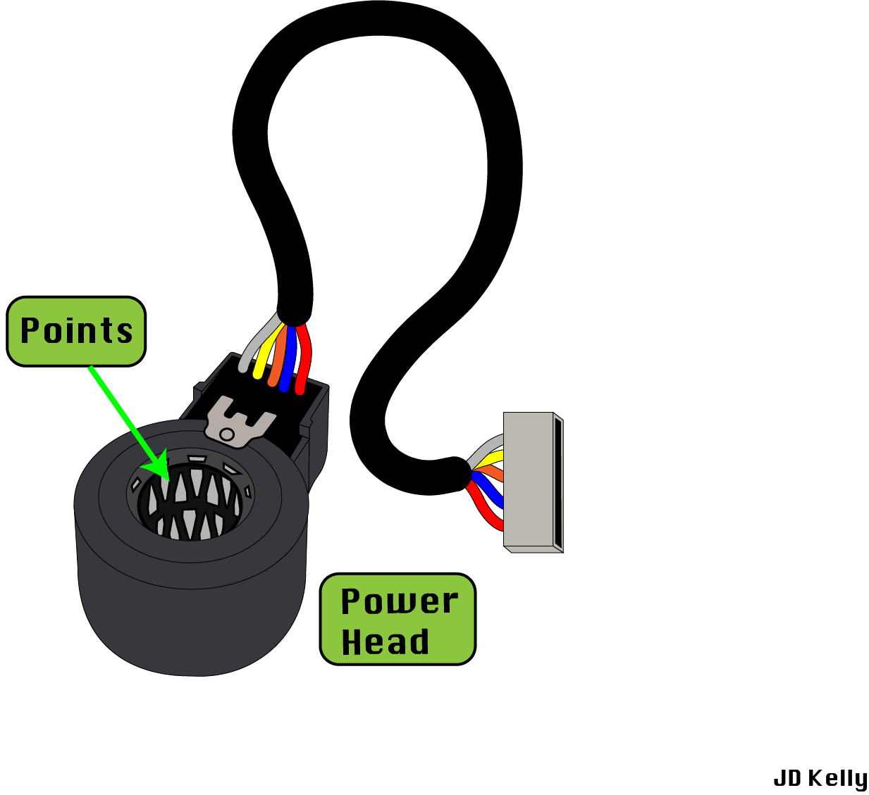
When these points are powered, they become magnetized in a sequential series of north and south pole designations that interact with the permanent magnet of the valve. As the points shift polarity, they turn the permanent magnet inside the valve, raising or lowering the flow-restricting needle.
Upon startup of the system, an audible clicking sound can be heard from the EEV as it fully opens and closes the pin to verify its position. Listen carefully for this sound, as it can help you troubleshoot an EEV. On some systems, an EEV that doesn’t complete this cycle may indicate a failed coil or a stuck pin. Typically, most manufacturers overdrive these valves closed to refind their position before operation. Unfortunately, diagnosing a failed EEV based on sound is difficult and subjective, so let's show you how to form a solid diagnosis.
If any of the four coils fail, the permanent magnet will no longer rotate. Remember that when a valve fails, there is no way to determine how open or closed it is.
The way I explain it to techs is: “It’s like pulling a domino out of a line. It stops the progression or movement of the valve.”
Testing the Power Head
A simple continuity test can be performed on the power head to determine if it is bad. This, again, is subjective to the manufacturer and who makes the EEV, so please read the appropriate service manual for the correct ohm values.
Start by unplugging the power head from the controller after the power to the control board has been turned off. Then, set your meter to ohms to check the resistance values of the power head coils.
It is important to identify the common wire first, as this will be the wire against which all other wires will be checked. In the example below, the red wire is common. Some EEVs will have six wires, but don’t panic! There is a secondary common on the EEV but it still only has four internal windings to test (two windings have a dedicated common)
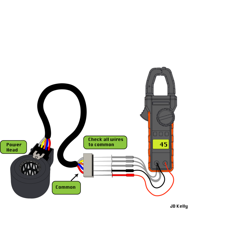
A rule of thumb is that you should read 40–50 ohms of resistance from each wire and common, plus or minus 10%. Any resistance reading lower than this will mean the winding has degraded and the coil has failed. You may also get OL which indicates an open winding which is also incorrect and the EEV should be replaced. This range can be anywhere from 26 ohms to 750 ohms based on the exact EEV that you are troubleshooting. Okay, last time I’ll say this: refer to the appropriate service manual for the correct values.
Testing the Valve
If the electrical coil passes the test, then your EEV is electrically sound, and you are ready to move on to the mechanical testing portion. We will want to perform a few tests on the valve to see if the plunger/needle has the free range of motion it needs to perform its job.
To test the valve, you will manually force the plunger up and down with a powered or non-powered EEV tool.
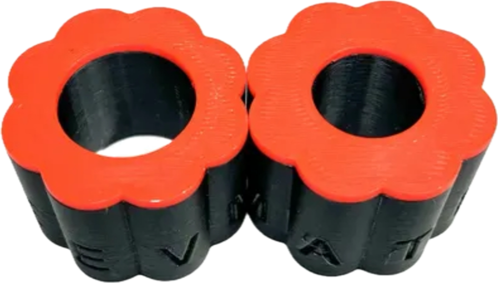
The non-powered option is a cylindrical plastic tool containing magnets. This tool goes directly on the valve body and is rotated in either a clockwise or counterclockwise direction to drive the plunger manually. You will be able to feel the magnets interacting with each other as you meet resistance while turning the tool. The goal is to drive the plunger and needle all the way down and all the way up without the plunger getting stuck. Remember that temperature correlates with pressure, and using a manual driver such as this also requires measuring temperature drop across the valve to ensure you are either fully open or closed.
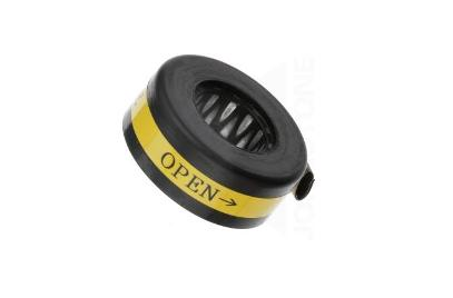
Also, if you think you can pop this on and relive your old DJ days, you will be sadly met with zero results. This type of tool requires slow and steady rotation to work effectively. Position it between the middle and the top of the valve body so that it aligns with the permanent magnet internally. Placing the manual tool at the bottom will miss the internal magnet completely.
EEVMATE also offers a cost-effective version of this tool if budget is a concern, as some of the tools offered by the factory are fairly pricey. Buy both, and you decide which you like best!
The powered option requires a tool like the EEVMATE to energize the coils and force the valve plunger all the way open or closed. It requires the power head to be seated on the valve body and disconnected from the control board. This tool may not be able to fix a damaged or failed EEV, but it will allow you to test it under normal conditions to form the correct diagnosis.
EEVMATE tool offers a “Turbo Mode” that allows you to drive the EEV at 10x the normal speed a control board would drive it at. This mode specifically allows you to drive EEVs with failed coil windings and stuck internal needles, which can be extremely valuable when attempting to stop refrigerant bleed-by in an evaporator coil. We tested this and found that even with two windings removed, the tool in “Turbo Mode” was still able to drive the valve. A word of caution is also to avoid unplugging and inserting EEVs’ plugs on main control boards while they are still powered, as there is a possibility of damage to the board under certain conditions.
The EEVMATE can be found at https://eevmate.com/.
 Related Tech Tips


Comments
To leave a comment, you need to log in.
Log In