
Get Tech Tips
Subscribe to get free tech tips.
Does your Kitchen Exhaust Suck?

Have you ever been tasked with installing the exhaust duct for a kitchen hood? I have, and when doing so, I wondered how to size the duct run correctly. Since I had a basic understanding of how airflow works, I knew that there had to be a limit on the resistance the fan can handle; more fittings added to the duct and longer runs equated to reduced airflow.
Residential duct design is performed by using a process called Manual D. I considered trying to calculate a friction rate for an exhaust fan by using the given equivalent lengths in ACCA’s Manual D. However, I reconsidered since I knew that supply ELs in Manual D are based on an arbitrary 900 FPM.
I decided to use my “phone-a-friend” option, and this time, I called my friend and mentor, Tony Amadilo. Tony is an engineer and owner of P.E. Load Calcs. My first question to Tony was, “Should I use the velocity correction for the equivalent lengths since it will be running at velocities much faster than 900 feet per minute?”
He said, “It's time I show you how to do your first commercial pressure drop calculation.” Man, I felt like Luke Skywalker getting ready to learn some Jedi mind tricks from Master Yoda himself. After learning this process, my mind was blown, and I figure there has to be someone else out there with the same struggle.

The steps are pretty simple, really. All you will need is a good Ductulator, a copy of ACCA’s Manual Q, and the blower curve for the fan you want to install.
STEP 1: First, we must look at the fan's spec sheet and reference the maximum design CFM and the corresponding static pressure. In this case, we are using model CP55IQ, which is rated for 600 CFM @0.1” W.C.
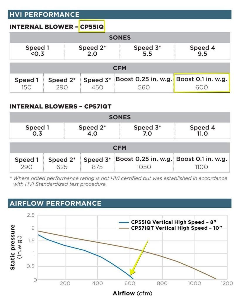
STEP 2: Next, we'll set the duct size on the Ductulator. The collar on this fan is 8” round, so let's try that. We line up 8” to the arrow under “Round duct diameter.” While holding the Ductulator still, we look at 600 CFM and note the corresponding velocity, which is around 1,720 FPM in this case. Also, we ought to note that the FR for galvanized metal duct is 0.55 (“W.C./100FT).
Note: If your Ductulator is giving you values that are a few percentage points off, consider a phone app Ductulator. These digital Ductulators give precise calculations and are not subject to assembly tolerances (a duct wheel that is a hair off-center will give incorrect results). An app is easier to use and looks like this:
“ASHRAE HVAC DUCT SIZER APP”

STEP 3: We need to convert our velocity of 1,720 FPM to velocity pressure, and the equation to do so looks like this:
VP = (V/4,005)2
- VP = Velocity Pressure (inches of water column)
- V = Velocity (FPM – Feet per minute)
- 4,005 is a unit conversion constant
0.18 = (1720/4005)2
Therefore, the velocity pressure in this example is 0.18.
STEP 4: Now, let’s calculate the friction loss for our actual straight duct. Let’s start by adding the total length of the duct run (not including elbows). In this example, it is 10 feet. Keeping our Ductulator set at 8” round, let's look at what the friction rate is for 600 CFM under “Galvanized metal duct.” In this case, it is 0.6” of friction loss for 100’ of duct. But we aren’t using 100’ of duct; the actual straight duct run is 10’, so let's do the math so that we can convert it to our actual friction loss. That equation looks like this:
PLSD = ADL x (FR /100)
- PLSD = Pressure Loss of Straight Duct in Inches of Water Column
- ADL = Actual Duct Length in Feet
- FR = Friction Rate
PLSD = 10 x (0.55/100) = 0.055” W.C.
This means that 0.06” is our pressure loss for 10’ of straight duct
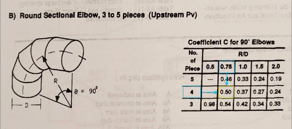
Step 5: Next, we must calculate the loss for all the 90s in the duct run. To do that, we count up the total number of 90s that will be needed for the duct run. For this job, I am figuring 4 elbows. Once you have the number of 90s, we look at Table A6-1 in Manual Q, “Loss Coefficients for Elbows.” I am using “Elbow B” because the elbows that I can buy locally are 4-gore. I don’t have an elbow in front of me, so I will assume the worst-case radius to diameter column, which is a loss coefficient of 0.5 per elbow.
Note: A 45° elbow pressure loss coefficient can be estimated to be half the value of a 90° elbow pressure loss coefficient.
Now, we can solve for the loss of each elbow, which looks like this:
PLCi = Ci x VP
- PLCi = Pressure Loss Per 90° Elbow
- Ci = Pressure Loss Coefficient for Fitting i, dimensionless
- VP = Velocity Pressure
PLC = 0.5 x 0.18 = 0.090 “W.C.
Therefore, 0.090 is the loss per 90° elbow, so if we want to find the loss of all our elbows, we just slightly adjust the math. Since we have just one single duct run with the same diameter (i.e., same velocity, therefore same velocity pressure) and fitting type (4 elbows), our total fitting losses equate to:
PLC-4 Elbows = (∑C’s) x VP = 4C-Elbow x VP
= 4 x 0.5 x 0.18 = 0.36” W.C. pressure loss for 4 elbows
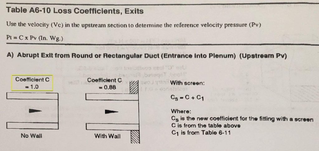
Step 6: We are almost there. We just need to take the wall cap exit into account. In this case, I referenced Table A6-10 in Manual Q. The most conservative, or largest, exit pressure loss coefficient is 1, so that’s what I will assume for a wall cap exit.
PLC-Exit = CExit x VP
- PLC-Exit = Total Exit Pressure Loss
- CExit = Pressure Loss Coefficient For a Wall Cap Fitting
- VP = Velocity Pressure
= 1 x 0.18 = 0.18” W.C. pressure loss for the wall cap exit
Step 7: Let’s add up all of our losses. The total pressure loss is:
PLTotal = ∑PLSD + ∑PLC’s = PL10’ + 4PLC-Elbow + PLC-Exit
= 0.055 + 0.36 + 0.18 = 0.595” W.C. total hood exhaust duct pressure loss
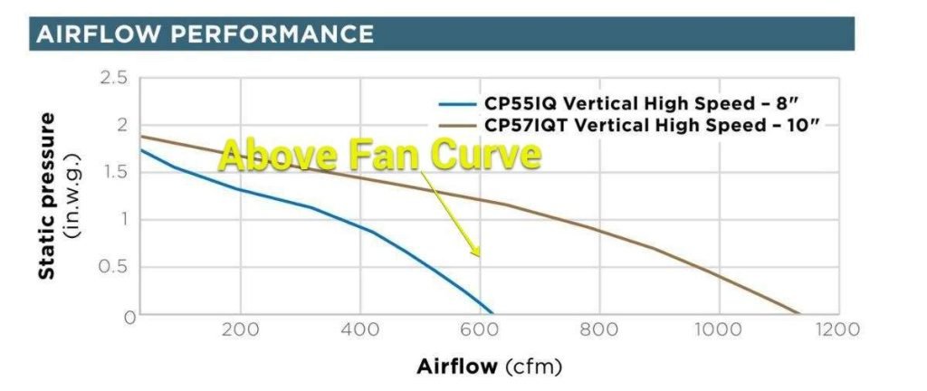
If we look at the system design point of 600 CFM @ 0.60” W.C., we can see that the total pressure loss of our 8” exhaust duct system is above the range hood blower curve, meaning our exhaust duct system resistance is too high. We want to size our exhaust duct such that our total pressure loss result is below, or exactly on, the hood blower curve such that we can meet or exceed the rated hood exhaust CFM. This is an iterative process that will sometimes take several tries to confirm the correct size duct. What duct size should be used to exhaust 600 CFM @ 0.1″ W.C. for the “CP55IQ” exhaust hood?
-Adam Mufich
 Related Tech Tips


Comments
To leave a comment, you need to log in.
Log In