Get Tech Tips
Subscribe to free tech tips.
5 Capacitor Facts You Should Know

One of the most common parts to fail on a single-phase HVAC system is the run capacitor, so much so that we sometimes refer to junior techs as “capacitor changers.” While capacitors may be easy to diagnose and replace, here are some things many techs may not know:
Capacitors Don't “Boost” the Voltage
A capacitor is a device that stores a differential charge on opposing metal plates. While capacitors can be used in circuits that boost voltage, they don't actually increase voltage themselves. We often see higher voltage across a capacitor than the line voltage, but this is due to the back EMF (counter-electromotive force) generated by the motor, not the capacitor.
Current Doesn't Flow Through the Capacitor
Techs notice that one side of power is connected to the C terminal, and the opposite side connects to the run winding. With this setup, it makes sense to imagine that this power “feeds” into the terminal, gets boosted or shifted, and then enters the compressor or motor through the other side. However, sensible as it may seem, that isn't actually how a capacitor works at all.

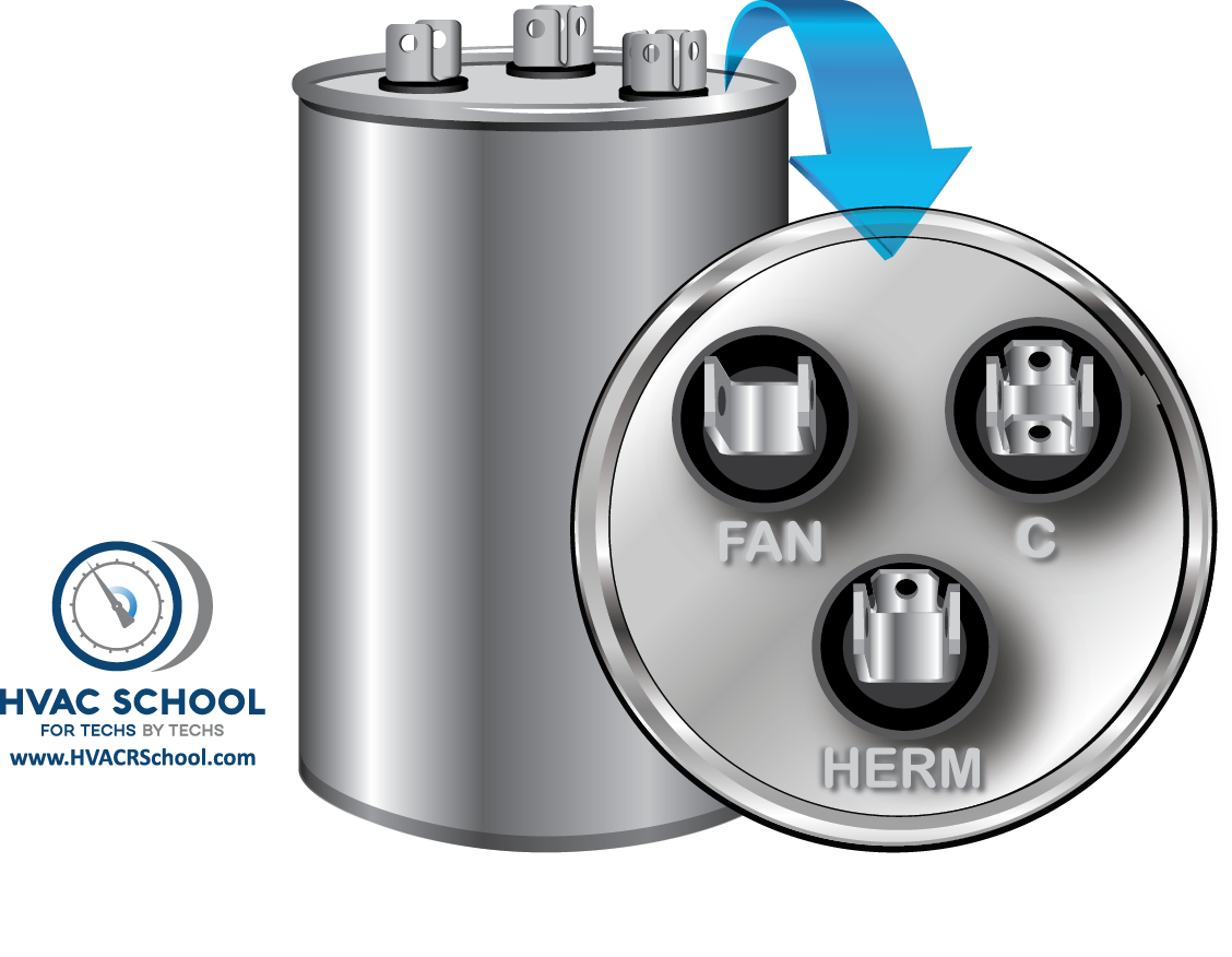
A typical HVAC run capacitor is just two long sheets of really thin metal, which are insulated with an insulation barrier of very thin plastic and immersed in oil to help dissipate heat. Just like the primary and secondary of a transformer, the two sheets of metal never actually touch, but electrons do gather and discharge with every cycle of the alternating current. For example, the electrons that gather on the “C” side of the capacitor never go “through” the plastic insulation barrier over to the “HERM” or “FAN” side. The two forces attract and release in and out of the capacitor on the same side they entered. Therefore, the current only goes into and out of the capacitor, not straight through it.
The Higher the Capacitance, the Higher the Current on the Start Winding
On a properly wired PSC (permanent split capacitor) motor, the only way the start winding can have any current move through is if the capacitor stores and discharges. The higher the MFD of the capacitor, the greater the stored energy, and the greater the start winding amperage. If the capacitor is completely failed with 0 capacitance, it is the same as having an open start winding. Next time you find a failed run capacitor (with no start capacitor), read the amperage on the start winding with a clamp to see what I mean.
That is why oversizing a capacitor can quickly cause damage to a compressor. By increasing the current on the start winding, the compressor start winding will be much more prone to early failure.
Voltage Rating Is What a Capacitor Can Handle, Not What It Will Produce

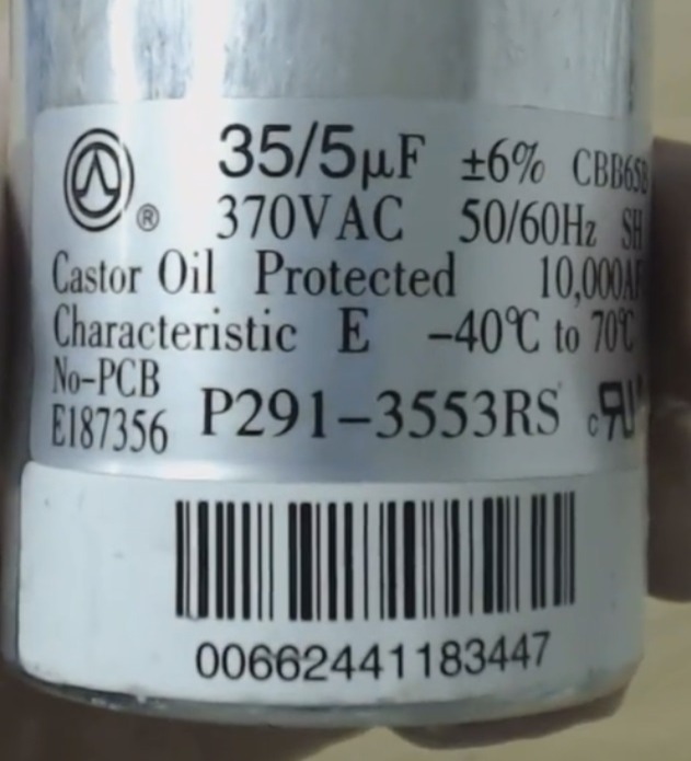
Many techs think they must replace a 370v capacitor with a 370v capacitor. The voltage rating displays the “not to exceed” rating, which means you can replace a 370v with a 440v, but you cannot replace a 440v with a 370v. This misconception is so common that many capacitor manufacturers began stamping 440v capacitors with 370/440 to eliminate confusion.
You Can Test a Capacitor While the Unit Runs
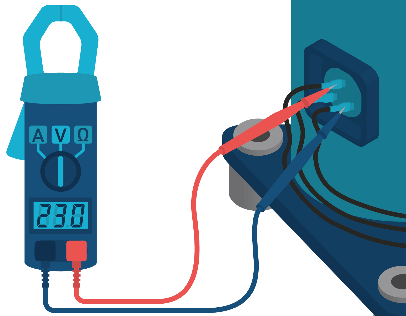
You simply measure the current (amps) of the motor start winding coming off of the capacitor and multiply it times 2652 (on 60 Hz power; that number changes to 3183 on 50 Hz power). Then, divide that number by the voltage you measure across the capacitor. For a full write-up on the process, you can look HERE.


Comments
Nice explanation thank you
Nice explanation thank you
You’re welcome! Great to hear it helped you.
You’re welcome! Great to hear it helped you.
That was awesome. I really like the drawn out diagram explaining how to test a capacitor while still in the circuit. I started checking capacitors like this on my preventative maintenance calls. Probably unnecessary but it makes me feel less like a janitor and more like a technician.
That was awesome. I really like the drawn out diagram explaining how to test a capacitor while still in the circuit. I started checking capacitors like this on my preventative maintenance calls. Probably unnecessary but it makes me feel less like a janitor and more like a technician.
Glad to hear it 🙂
Glad to hear it 🙂
👍
👍
Quality content and the production value is much appreciated!
Quality content and the production value is much appreciated!
Glad to hear it!
Glad to hear it!
Question on Combining Caps. I know that if I parallel two cap the UF is added and if I string them in series you can use the Formula 1/ 1/C1 +1/C2 +1/C3 ect. to get the total Capacitance. my question that I have does the Voltage rating change when strung in series. since ohms law teaches that Et= E1+E2+ E2 in series. Ive heard some say yes and some say no
Question on Combining Caps. I know that if I parallel two cap the UF is added and if I string them in series you can use the Formula 1/ 1/C1 +1/C2 +1/C3 ect. to get the total Capacitance. my question that I have does the Voltage rating change when strung in series. since ohms law teaches that Et= E1+E2+ E2 in series. Ive heard some say yes and some say no
Let me clear this matter up. If you take 2 identical capacitors and then you series them together the total voltage handling rating would double but the capacitance would then become 1/2. You should also add 2 equal value voltage diving resistors (one across each capacitor) to insure each cap has the same voltage across it. As an example if you take 2 – 40 microfarad caps rated at 370 volts and you series them you would wind up with a 20 microfarad cap rated at 740 volts. Now if you measure these 2 capacitors in a charged-up state you would get 1/2 the voltage on each cap that you would get with a single cap so the end results would be the 2 capacitors acting as one capacitor. They won’t change the overall measured stored voltage and that voltage would remain the same as if there were only one capacitor in the unit.
Let me clear this matter up. If you take 2 identical capacitors and then you series them together the total voltage handling rating would double but the capacitance would then become 1/2. You should also add 2 equal value voltage diving resistors (one across each capacitor) to insure each cap has the same voltage across it. As an example if you take 2 – 40 microfarad caps rated at 370 volts and you series them you would wind up with a 20 microfarad cap rated at 740 volts. Now if you measure these 2 capacitors in a charged-up state you would get 1/2 the voltage on each cap that you would get with a single cap so the end results would be the 2 capacitors acting as one capacitor. They won’t change the overall measured stored voltage and that voltage would remain the same as if there were only one capacitor in the unit.
Hi Pat,
The voltage rating does not change. Capacitors are not batteries that create a charge and whos charges are added when connected in series. Instead, capacitors are theoretically charged up to the maximum voltage applied. However, when used with diodes they can be used to make DC voltage multipliers. This video is a bit outside the trade but you may take something away from this guy’s explanation of DC voltage multipliers https://www.youtube.com/watch?v=ep3D_LC2UzU
Hey Ed. I completely agree with you. I was originally told that the voltage rating dosn’t change but like a lot of things in this trade everyone has a different opinion. And I was just looking to aee if ive missed somthing!
Cheers!
Hey Ed. I completely agree with you. I was originally told that the voltage rating dosn’t change but like a lot of things in this trade everyone has a different opinion. And I was just looking to aee if ive missed somthing!
Cheers!
The values shown in the pic for cap testing under load: are these just random numbers or represent a real world example?
The reason I ask is: i’m assuming this is a 240v system, with the voltage of 292 across H and C. And the amperage of 7.8 would be something to expect from a typical residential AC compressor.
But a 70mic/farad cap? Seems double of what I’d expect.
Anyone have any comment on this formula?
This helps for faster Diagnosis. In the trade for A year and 7 months trying to gain the Habits of Blue Collar early!!
This helps for faster Diagnosis. In the trade for A year and 7 months trying to gain the Habits of Blue Collar early!!
Came here from YouTube to write down the cap test calculation. I knew I Would learn something from the podcast, even if it was just about capacitors. You clearly are putting a lot of effort and love in this project. wish you the best. Greetings from Dominican Republic! By the way, that podcast with the legend Dick Wirz was awesome!
Came here from YouTube to write down the cap test calculation. I knew I Would learn something from the podcast, even if it was just about capacitors. You clearly are putting a lot of effort and love in this project. wish you the best. Greetings from Dominican Republic! By the way, that podcast with the legend Dick Wirz was awesome!
Thanks for your feedback. I’m glad it helped you.
Thanks for your feedback. I’m glad it helped you.
Hi, Thank you for explaining how to calculate the Capacitance of a capacitor when it is running or under load. The only thing I would suggest here is to let people know that the constant 2652 comes from 1/(2*3.1416* frequency) AND ALSO the conversation to uF. I was confused for a while because if you just do the calculation per the formula then your capacitance will be in farads only and then we can convert it in to microfarads, milli
farads etc…
V=IR; R= Xc; XC =1/(2*3.1416*f*C);
C=I/1/(2*3.1416*f*V) or C = (.002652*I)/Voltage; where C units are farads (microfarads) and frequency is 60 Hz.
Thanks again!!
Correction. “where C units are farads (not microfarads)”
Correction. “where C units are farads (not microfarads)”
Comp start wire and comp run wire are reversed in diagram
Comp start wire and comp run wire are reversed in diagram
I read the terminal connected to the cap plate closest to the capacitor can is supposed to be connected to line voltage instead of motor windings to protect windings in case of a cap short to ground. I cannot find out which color that term is, white or black. Amrad 15mfd run cap on PSC. Thanks.
I read the terminal connected to the cap plate closest to the capacitor can is supposed to be connected to line voltage instead of motor windings to protect windings in case of a cap short to ground. I cannot find out which color that term is, white or black. Amrad 15mfd run cap on PSC. Thanks.
Good to hear the explanation thanks.
Good to hear the explanation thanks.
Interesting stuff, I’m more a Uninterruptible Power Supply (UPS) Tech where caps are used in series/parallel configurations. Being forced to learn some basic HVAC troubleshooting. One thing I noticed is that my 480Vac BARD HVAC has a 10MFD 370Vac run capacitor with 460Vac across it. The motor only draws about 1.6A. This is a brand new unit just being installed.
Interesting stuff, I’m more a Uninterruptible Power Supply (UPS) Tech where caps are used in series/parallel configurations. Being forced to learn some basic HVAC troubleshooting. One thing I noticed is that my 480Vac BARD HVAC has a 10MFD 370Vac run capacitor with 460Vac across it. The motor only draws about 1.6A. This is a brand new unit just being installed.
I believe the following is not correct: ” We often see higher voltage across a capacitor than the line voltage, but this is due to the back EMF (counter-electromotive force) generated by the motor, not the capacitor”. I’m fairly certain that CEMF is always less than the applied Voltage in an a/c motor. Regardless, I believe that the higher Voltage seen in a Cap in series with the Start winding is due to the fact that the cap is wired such that it is connected across both windings (Start and Run) even though the windings are electrically wired in parallel so the cap is seeing the total Voltage of the 2 windings where one is up to 90 degrees out of phase. It’s this phase shift that results in a combined higher voltage. My PSC compressor motor cap has 337 Vac across it while runnning with a 240 Vac supply going to each winding. This Voltage checks out with what it should be when checking the functionality of the capacitor during operation (winding amps x 2652/cap Voltage = MFd.
I believe the following is not correct: ” We often see higher voltage across a capacitor than the line voltage, but this is due to the back EMF (counter-electromotive force) generated by the motor, not the capacitor”. I’m fairly certain that CEMF is always less than the applied Voltage in an a/c motor. Regardless, I believe that the higher Voltage seen in a Cap in series with the Start winding is due to the fact that the cap is wired such that it is connected across both windings (Start and Run) even though the windings are electrically wired in parallel so the cap is seeing the total Voltage of the 2 windings where one is up to 90 degrees out of phase. It’s this phase shift that results in a combined higher voltage. My PSC compressor motor cap has 337 Vac across it while runnning with a 240 Vac supply going to each winding. This Voltage checks out with what it should be when checking the functionality of the capacitor during operation (winding amps x 2652/cap Voltage = MFd.
olympe: olympe casino avis – casino olympe
olympe: olympe casino avis – casino olympe
To leave a comment, you need to log in.
Log In