
Get Tech Tips
Subscribe to get free tech tips.
Universal Condenser Fan Wiring Options

Assessing the Situation
It is fairly common for a service technician to come across a failed condenser fan motor in the field. It doesn’t matter if we are talking about really old or fairly new equipment—condenser fan motors sometimes fail. The issue is deciding whether to use an OEM (Original Equipment Manufacturer) or a universal replacement motor. There are pros and cons to both. Using an OEM motor will be a relatively easy change out, but sometimes, due to availability, they might not be the best choice. Universal motors, on the other hand, are readily available and, depending on the brand, could meet or exceed the OEM in quality and dependability.
For the purposes of this article, let’s assume the customer isn’t willing to wait for the OEM part, so you decide to use a universal motor. The problem is that the failed motor is a 3-wire type motor, and the universal motor is a 4-wire configuration. You have two options in this scenario: add another run capacitor for the 4-wire design or configure the universal motor to be wired to operate as the 3-wire motor.
Let’s look at both options so we can add this simple little technique to your tool bag.
4-Wire Setup
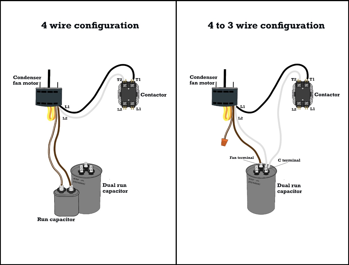
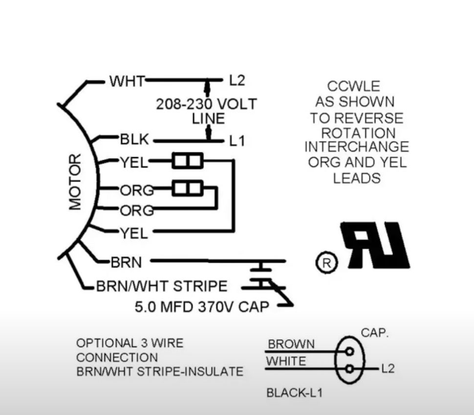
To begin with, let's take a look at the 4-wire setup shown in the wiring diagram below.
This is how the universal motor is intended to be wired out of the box. One major difference from the 3-wire configuration is that the 4-wire setup requires adding an additional run capacitor to the equipment.
Notice in the diagram that the wires denoted BRN and BRN/WHT STRIPE call for a 5.0 MFD 370v Capacitor.
Wire Designations
The image below shows a solid brown wire, which is the capacitor lead, and a brown-and-white wire that is considered the capacitor common. These wires connect directly to a run capacitor. It doesn’t matter which terminal they are connected to as long as they are on separate terminals of the capacitor.
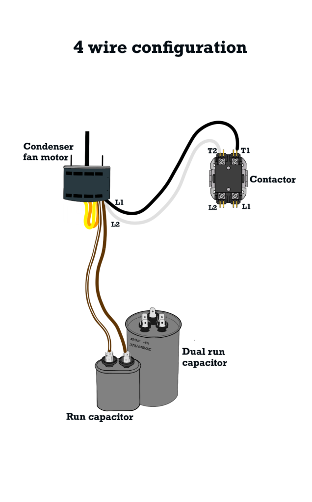
In this case, the two power wires—L1 and L2—are white and black and will mount to the T1 and T2 terminals of the contactor. These wires supply high voltage to the condenser fan motor once the contactor closes.
The orange and yellow wires are the fan rotational wires. Switching these wires will change the rotational spin of the fan.
Internal Wiring
If we take a closer look at how the 4-wire universal fan motor is internally wired, we will see that the brown-and-white wire is connected to the white power wire within the casing of the motor. These wires are essentially the same, and if you were to ohm these wires out, you would find that there is no resistance.
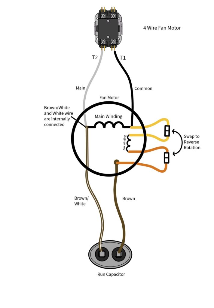
Because these wires are the same, it is possible to convert the 4-wire to a 3-wire setup by cutting and capping the brown-and-white wire. This practice won’t make the motor any better or worse. It simply gives you the option of not having to add another capacitor to the system.
While adding another capacitor may not seem like a big deal, you may find yourself in a situation where space is limited and this simple but useful technical skill could make a huge difference on a service call.
Now, let’s take a look at what the conversion will actually look like.
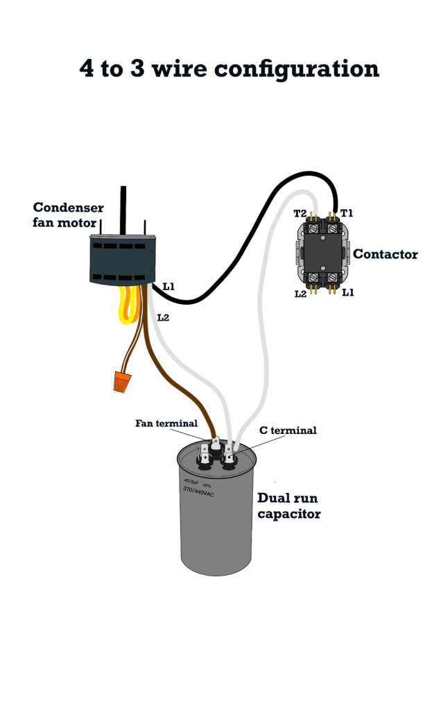
Converting a 4-Wire Motor to a 3-Wire Configuration
Notice in the image below that the brown-and-white wire has been capped. It is important to cap this wire, as it contains high voltage that could cause substantial risk to human safety and damage the equipment if left open and unsecured.
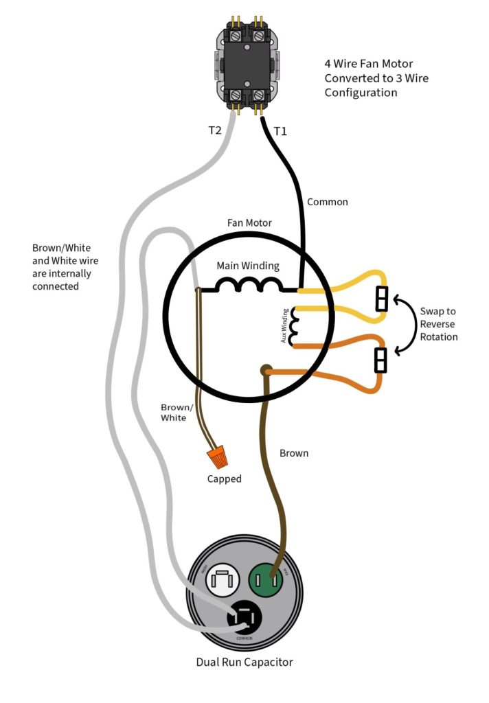
Once the brown-and-white wire is eliminated, we can start connecting the remaining wires. The black wire connects to the T1 terminal of the contactor. The solid brown wire connects to the terminal labeled FAN on the dual run capacitor. The white wire will connect to the C terminal and be jumped to the T2 of the contactor.
Conclusion
As you can see from the illustration, the reality is that a 4-wire and a 3-wire motor are pretty much the same. It all depends on the application and which method you want or need to apply to accomplish the job.
I think that it comes down to personal preference and the physical design of the equipment. If there is plenty of room and a place to properly strap the additional run capacitor, then the 4-wire setup may be the way to go.
As for me, I usually prefer converting to the 3-wire setup. I have come across quite a few units where the previous tech left the run capacitor taped up in its box and dangling in the condenser cabinet. No judgment because I don’t know what the circumstances were when they made that choice, but I think that for me, it makes sense to go ahead and make the conversion, replace the dual run capacitor, and tie all the wires down in a neat and orderly fashion.
For more information on this concept, check out HVAC School’s 3D animated video at https://www.youtube.com/watch?v=VdAktO80If0.
—JD Kelly
 Related Tech Tips


Comments
To leave a comment, you need to log in.
Log In