
Get Tech Tips
Subscribe to get free tech tips.
20° ΔT (Delta T), A Lazy Rule of Thumb


What should the delta T (ΔT) be?
What do you mean!? 20 degrees, of course!
We are referring to the air temperature drop across an air handling unit or evaporator coil in cooling mode. Actually, depending on who you ask, the answer will range between 18-22 degrees Fahrenheit. Heck, I’ve heard some insist that the ΔT across a properly operating air conditioner should always be 20 degrees, even if it were installed in the middle of a football field! No, really, that's quite literally a true story.
This is one of the most established and misleading rules of thumb in our industry. Yes, that’s right. I said misleading! Don’t get me wrong; getting an accurate measurement of what the ΔT is on an operating system has a lot of value. However, because it’s so simple to do and it doesn’t require a particularly expensive tool to measure it, there is a lot of abuse and misuse of it.
If we measure ΔT while diagnosing a system, and it happens to be at a range that has been deemed acceptable by lack of information and bad habits, we’d be poised to make avoidable mistakes repeatedly. Creating, like this, some bad habits of our own.
When we measure ΔT, we only measure how much sensible heat was removed from the return air. In providing human comfort, air conditioners are not only tasked with removing sensible heat; there is also a good chunk of latent heat removal that has to occur—at least here in South Florida.
The rate of removal between sensible and latent is called sensible heat ratio (SHR); you can read more about it HERE, and please, take the time to read the two comments below the article (especially the first the one by Jim Bergmann), as they offer a simpler way to project the supply air temperature. It would only, however, predict the dry-bulb temperature. To consider the latent heat removal and provide an intersecting point, the calculation has to go a little differently; this way, we would be working with the total capacity.
Ok, so what should the ΔT be then? Assuming a given airflow and proper refrigerant charge, it depends on the temperature and water vapor content of the air entering the evaporator coil. It does not depend on how many years of experience the person that you are asking has.
Because the purpose of this article is to emphasize the change in ΔT with varying return air conditions, we are going to assume proper system performance with 400 CFM per ton. Don’t worry; it could also be predicted with different airflows (I prefer to be closer to 350 CFM per ton myself), but to streamline the calculations, we’re going to use a standard airflow that most are familiar with.
There are a few things we need to start:
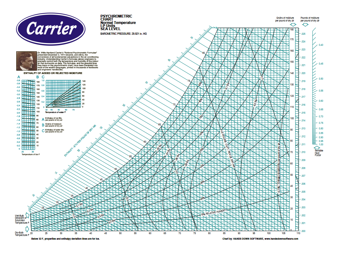
- A psychrometric chart:
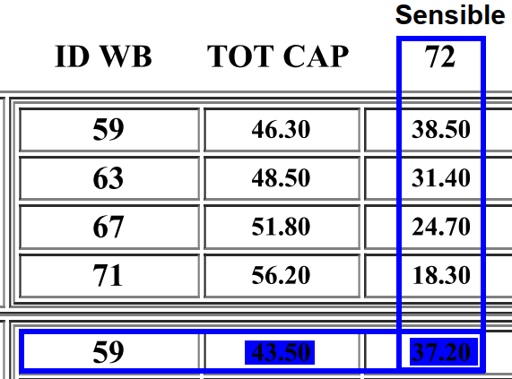
- A manufacturer’s extended performance data:

- The total capacity formula at standard air conditions:
BTU/H = CFM x 4.5 x (Eh – Lh)
Where
CFM – Air volume being moved across the evaporator coil
4.5 – 60 (min. in an hour) multiplied by .075 (the density of air at standard conditions)
Eh – Entering air enthalpy
Lh – Leaving air enthalpy
3a. We need to solve for Lh:
Lh = Eh – BTUH / CFM x 4.5
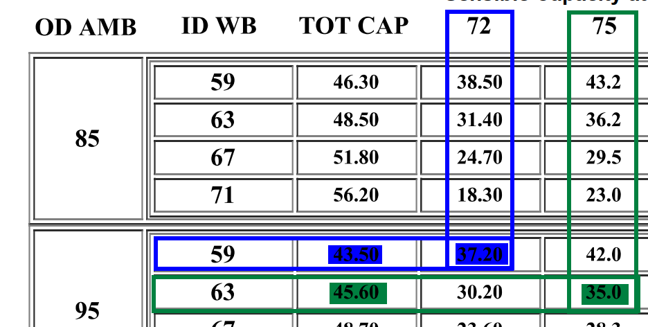
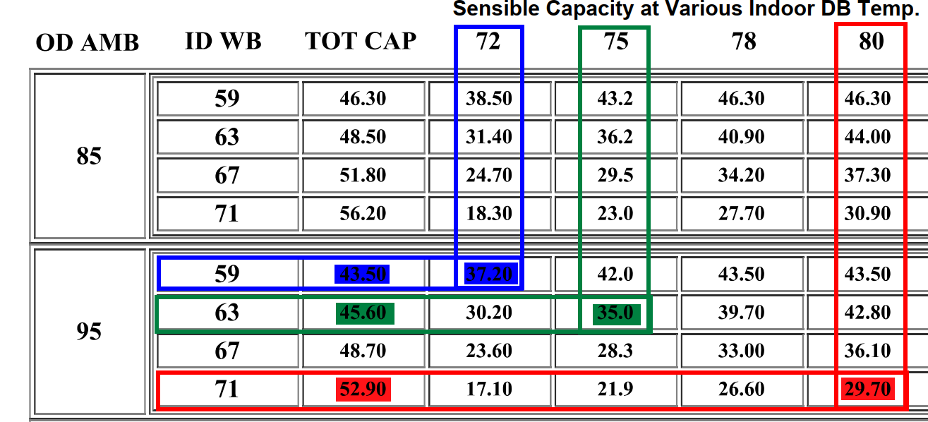
We now need to pick which conditions we’re gonna use to run these examples. I’ve highlighted them in color for ease and convenience. See below.

Next, we need to identify in the psychrometric chart:
- The dry bulb temperature scale
- The sensible heat ratio scale
- The enthalpy scale
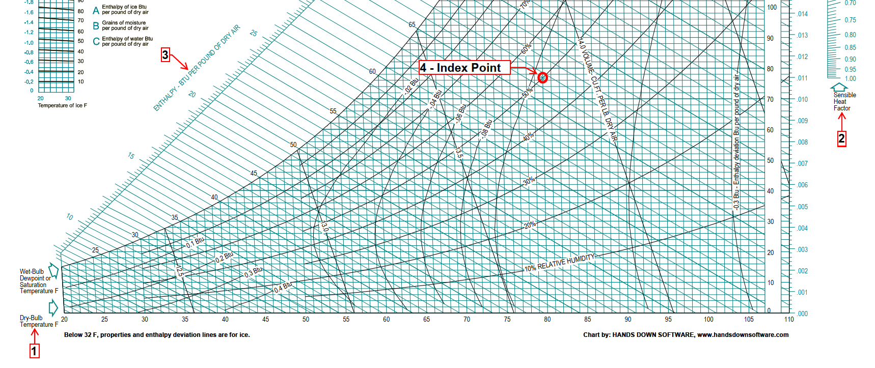
- The index point
Outlining the procedure
For our first example, we are going to use our “blue” conditions. These are the colder and drier conditions of the three. At 72 degrees dry-bulb and 59 degrees wet-bulb, this system will produce a total capacity of 43,500 BTU/H, of which 37,200 represent sensible heat removal. This will yield an 85% SHR (37,200 / 43,500 x 100 = 85%).
The steps to plot the lines we need on the psychrometric chart are:
- Find the point that marks the return air characteristics at the intersection of 72 degrees DB and 59 degrees WB.
- Draw a straight line from our .85 SHR to the index point on the chart.
- Plot out from the return air conditions intercept to the enthalpy scale to find the BTU content per pound of air. In this case, the specific enthalpy of this air is 25.6 BTU/pound of dry air.
- From the rearranged total capacity formula, calculate our leaving air (supply) enthalpy plot down diagonally from the left following the enthalpy lines. In this case, it looks like this:
Lh = Eh – BTUH / CFM x 4.5
Lh = 25.6 – 43,500 / 1600 x 4.5
Lh = 25.6 – 43,500 / 7200
Lh = 25.6 – 6.04
Lh = 19.56 (round it up to 19.6)
- Draw a line that is parallel to the SHR line on step 2, but that runs across our entering air conditions. Keep going until it intercepts the supply air enthalpy drawn on step 4. This is the process line for the current SHR; at this intercept, find our supply air characteristics.
- Plot straight down from the supply air point to find the leaving air DB temperature.
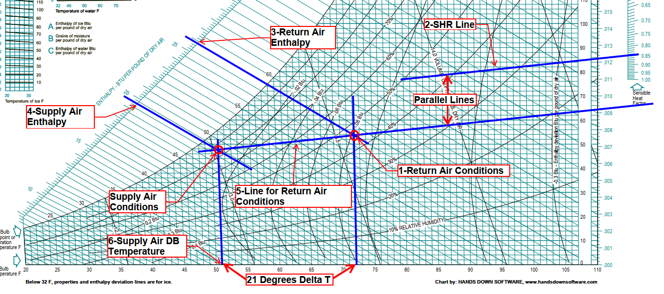
It looks like this:
In this first example, the aforementioned 20 degrees ΔT rule of thumb holds under these conditions. That is, with air entering the evaporator coil at 72 degrees DB and 45% RH.
Take 2
Let’s try our second set of conditions. With the “green” conditions, we have our entering air at 75 degrees DB and 63 degrees WB, and we are approximately at 75% SHR.
I’m going to spare you the tedious description of every single step again. But once we plot all our lines as we did in our first example, this is what they look like on the chart:

The rule of thumb remains strong! This is with 75 degrees of DB and 51% RH. As the case may be on most homes where the A/C system was thoughtfully sized for the load, and we might’ve found ourselves there doing a PM.
It got hot and humid!
But what happens when we plot our “red” set of conditions at 80 degrees DB, 71 WB, and 56% SHR?
This is what it looks like:

Rule of thumb busted!
Unless you are an apprentice running maintenance (nothing wrong with that), most of us find ourselves knocking on customers’ doors because their system isn’t cooling for whatever reason.
If we are responding to a service call where the A/C system hasn’t been working for a number of hours, or maybe a couple of days in the middle of the summer, is it unthinkable that by the time we get the system back up and running, it is 80 degrees in the space with the relative humidity in the mid-60s? I would say no. It’s actually very likely.
Same thing if we are doing a changeout. The house has had the whole day to warm up and build up some extra water vapor before the new system it’s ready to be turned on and commissioned. What do you think the conditions of the return air will be then?
But wait for a second, Mr. I-can-draw-colored-lines-on-a-psych-chart! I’ve been doing this for 45 years, and I know I’ve measured ΔTs at 20 degrees under all kinds of conditions! Heck, I’ve gotta look for it, but I’m pretty sure I’ve got a Polaroid shot somewhere to prove it.
I believe it! What are the chances that ΔT readings have been and are still being taken on systems with PSC motors and questionable duct designs for the last 30 years? Or even before? I’d say pretty good. In fact, I have a strong suspicion that that’s where this misunderstood rule of thumb might’ve come from.
Needless to say, it is not practical to run all these calculations when diagnosing in the field. That’s what measureQuick is for. The larger point is—and to copy Jim Bermann’s argument—why are we checking the supply air temperature with a $14 thermometer if we don’t know what it should be really?
Without knowing what the water vapor content of the return air is, we can’t predict the supply air temperature. Ditch the thermometer and invest in a hygrometer. That way, you can measure the moisture content of the air entering and leaving the unit, in addition to the ΔT, if you still want to hang on to that.
By the way, if you were to find yourself near the local YMCA this summer and see an air conditioner installed in the middle of a football field, check the ΔT. In the best-case scenario, it’ll be 10 degrees.
—Genry Garcia
 Related Tech Tips


Comments
To leave a comment, you need to log in.
Log In